
Most scrubber pages answer a different question than the one your plant asks. They describe what a packed tower does; you need to know which control device your exhaust needs at all. Industrial exhaust treatment is a routing problem: the pollutant form—soluble gas, poorly soluble VOC, or particle—selects the device family. This library answers with a six-row process matrix—semiconductor, glass, plastics extrusion, automotive, and cyanide electroplating—that names the pollutant form each stream carries, the device family that can actually remove it, and the one decision that makes or breaks the route. For processes not on the list, a three-question solubility and temperature screen classifies any stream in minutes, and a worked example shows how a mixed extrusion line splits into a defensible control train. You finish with the eight-input data checklist a supplier needs to turn the route into a quotation.
Key Takeaways
- The pollutant form selects the device: soluble and reactive gases absorb in a wet scrubber, poorly soluble VOCs go to oxidation or carbon, and particles and mist need filtration or capture.
- The process matrix routes five process families—semiconductor, glass, plastics extrusion, automotive, and cyanide electroplating—to their owner guides, each row carrying the decision that matters first.
- Solubility separates a fit from a miss: HCl scrubs at percent-level removal while styrene sits near 300 ppm water solubility, so the same tower that absorbs one stream only humidifies another.
- Temperature and moisture are design inputs: glass furnace gas arrives near 250–500 °C and needs quenching, and gas above roughly 80 °C exceeds the continuous-service limit of polypropylene packing.
- Gather flow, temperature, concentration, and capture data before any quote; the closing checklist lists exactly what to collect.
Industrial Exhaust Treatment: The Process-to-Pollutant-to-Device Matrix
Use this matrix like a routing table: find your process row, read the pollutant form, check the device family, and open the owner guide for the full method. The decision column names what makes or breaks the route.
| Process | Typical pollutant form | Device family | Core decision | Owner guide |
|---|---|---|---|---|
| Semiconductor / electronics | HF, HCl, NH₃, silane particles, PFCs | Packed-bed alkaline scrubbing upstream of PFC abatement; pre-wash for silane | Acid gases absorb first; PFCs never absorb and need thermal or catalytic destruction; fab tools typically exhaust 200–2,000 CFM per chamber | Packed-bed acid-gas scrubber design for semiconductor exhaust |
| Glass furnace | SOx, HF, condensable sulfates/halides, metal HAP, hot gas | Multi-stage wet scrubbing (quench + venturi + packed tower) or dry sorbent + filter | Condensables and acid gas together defeat a bare filter; inlet gas near 250–500 °C decides the route | Multi-stage wet scrubbing system for glass manufacture |
| Plastics extrusion | HCl or formaldehyde (soluble), styrene/alkanes (poorly soluble), oil mist and fume | Venturi prescrubber + packed tower for the soluble fraction; carbon or oxidation for the rest | The polymer sets the chemistry: PVC and acetal lines pass a wet-scrubber fit test; PS and PE lines usually do not | Wet scrubber fit for plastics extrusion exhaust |
| Automotive manufacturing | Paint solvents (VOC/HAP), weld fume, grinding dust, machining mist | Oxidation or carbon for paint vapor; filters and mist collectors for fume and mist; scrubber only where gas absorbs | Route each of the six emission sources separately; paint booths hold at least 100 fpm face velocity and most automotive exhaust is not a scrubber job | Air pollution control for automotive manufacturing |
| Cyanide electroplating | Hydrogen cyanide vapor, acid mist | Local exhaust first, then alkaline scrubbing of the controlled stream | Capture and segregation come before any scrubber; the 10 ppm PEL and 4.7 ppm ceiling limits make this a safety-gated route | Cyanide electroplating local exhaust ventilation |
| Solvent / VOC-dominated stream (no acid gas) | Non-polar or sparingly water-soluble organics, odour compounds, some HAPs | Activated carbon adsorption, with a pre-filter where particulate is present | Adsorption is a capture-and-hold route, not a destruction route: the bed holds what it takes until breakthrough, so spent carbon handling, regeneration or disposal and a breakthrough monitoring plan are part of the design. Confirm the carbon type and grade against the actual compound list, humidity and temperature before specifying a bed | Carbon adsorption versus wet scrubbing |
| Acid gas where water supply or liquid-waste handling is the constraint | Acid gases (HCl, SO₂, HF) plus particulate, in a cool and dry stream | Dry sorbent injection upstream of a fabric filter or electrostatic precipitator | No scrubbing liquid and no liquid effluent, but the reaction product leaves as a solid waste stream that has to be characterised, handled and disposed of, and reagent consumption rises with inlet concentration. Whether it can reach a given outlet limit depends on the sorbent, the stoichiometric ratio and the inlet loading, so verify the achievable removal for the duty rather than assuming it | Dry versus wet scrubber selection and cost |
| General / uncertain stream | Mixed gas and particulate | Start with the three-question screen in the next section | When the pollutant form is unclear, classify before you buy | Industrial scrubber principles guide |
The matrix is the navigation layer of this library; each owner guide owns the detailed method. If your process does not appear above, apply the three-question screen next—it is the same logic every matrix row uses.
Start With the Pollutant, Not the Device
How the Three Questions Route the Stream
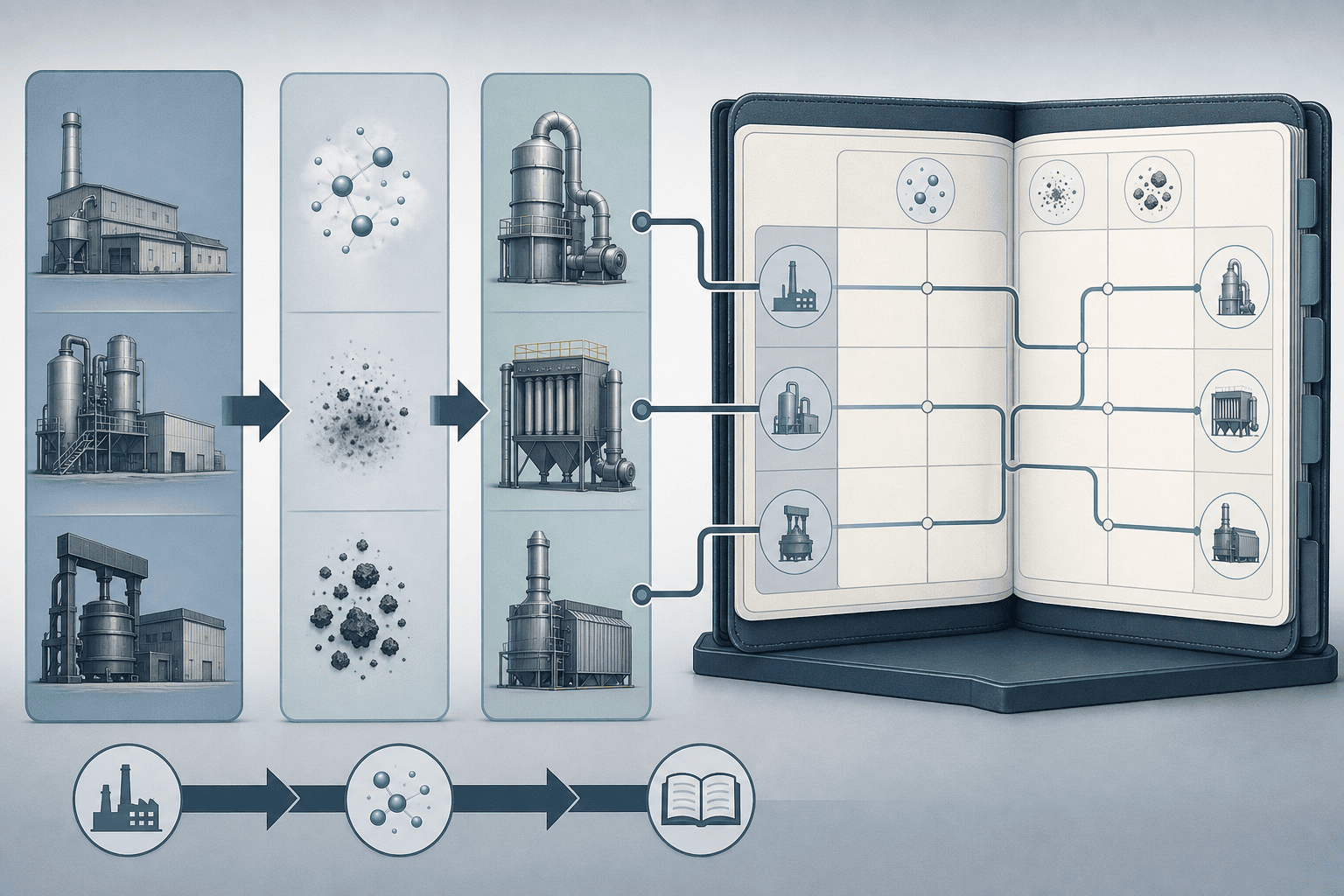
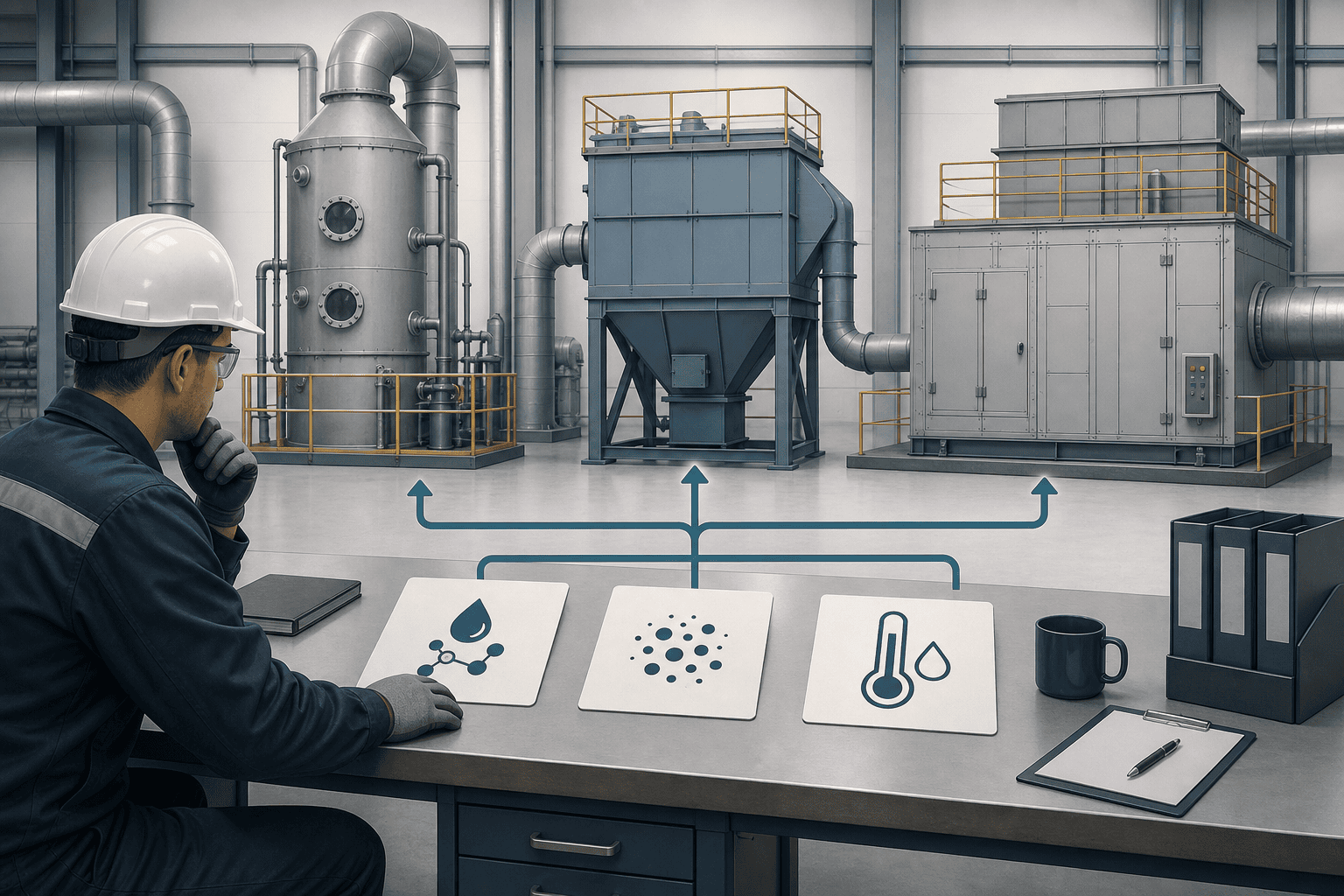
The device family follows the pollutant form, and three questions decide that form. First, does the pollutant dissolve or react in water? Soluble acid gases—HCl, HF, SO₂, NH₃—transfer into a scrubbing liquid, and a typical packed section provides roughly 0.5–1 s of gas residence time: enough for a fast hydrolysis reaction, not for a slow, poorly soluble transfer (source: XICHENG packed-bed and VOC-control guides). Second, is it a particle or an aerosol rather than a gas? Weld fume, oil mist, and condensable smoke do not absorb; they need inertial or barrier capture in a venturi, filter, or mist collector. Third, what temperature and moisture does the stream carry? Hot, saturated gas needs quenching before polymer or fiberglass construction, and gas above roughly 80 °C already exceeds the continuous-service limit of polypropylene packing on many towers (source: XICHENG plastics-extrusion guide).
| Question | If yes | If no | Route |
|---|---|---|---|
| Does it dissolve or react in water? | Absorption stage fits (packed tower with reagent) | Solubility ceiling: water-only scrubbing removes roughly 30–50% of aromatic VOCs | Carbon adsorber or thermal oxidizer |
| Is it a particle, fume, or mist? | Capture stage fits (venturi, filter, mist collector) | Gas-phase handling only | Venturi prescrubber ahead of absorption |
| Is the stream hot or saturated? | Quench before the tower; verify packing material limit | Direct contact with wetted packing | Quench stage or heat recovery |
The Solubility Test in Numbers
The solubility test is the same one the process rows apply. Styrene illustrates the ceiling: its water solubility sits near 300 ppm at 20 °C, while HCl removal works in percentages—three orders of magnitude apart (source: XICHENG plastics-extrusion and automotive guides). That gap is why a packed tower can promise caustic scrubbing for an acid gas and only humidification for a styrene stream. Solvent-assisted absorbers reach an upper bound around 40–65% on generic aromatic VOC service—vendor-published ranges that describe why poorly soluble streams route to carbon or oxidation instead (source: XICHENG VOC scrubber guidance). Decide the form first; the device family follows automatically, and the multi-stage selection resource carries the configuration comparison from there.
Semiconductor Exhaust: Acid Gases First, Then PFCs
Four Process Classes, Four Treatment Stages
Semiconductor exhaust is the case where wet scrubbing is mandatory but never sufficient alone. A typical fab tool exhausts about 200–2,000 CFM per process chamber, and the chemistry drives the train: hydrogen fluoride from oxide etching, hydrogen chloride from cleaning, ammonia from silicon-nitride deposition, pyrophoric silane, and perfluorocompounds from chamber cleaning (source: XICHENG semiconductor exhaust treatment guide). HF and HCl absorb into caustic liquor near pH 8–10; ammonia needs a separate sulfuric-acid loop near pH 2–5 because mixing the two streams forms solid ammonium salts downstream (source: XICHENG semiconductor exhaust treatment guide).
| Process class | Main pollutants | Treatment stage |
|---|---|---|
| Etch (plasma) | HF, SiF₄, unreacted PFCs | Caustic packed-bed scrubber, then PFC abatement |
| Cleaning (RCA, piranha) | HCl, H₂SO₄ mist, NH₃ | Acid scrubber; ammonia separated to its own loop |
| CVD deposition | Silane, NH₃, HCl | Water-wash or cyclone for silica, then scrubber |
| Chamber clean | PFCs (30–50% of fab PFC load) | Point-of-use plasma or thermal abatement |
Why PFCs Break a Scrubber-Only Plan
The boundary that breaks a wet-scrubber-only plan is the PFC family. CF₄, C₂F₆, and SF₆ are chemically inert in a caustic tower and pass through unreacted; they are greenhouse gases roughly 6,500–23,900× more potent than CO₂, and chamber cleaning alone consumes about 30–50% of a fab’s PFC load (source: XICHENG semiconductor exhaust treatment guide). Point-of-use plasma abatement typically destroys more than 95% of PFCs at the tool exhaust, while centralized systems run lower—so the scrubber captures what dissolves and the abatement stage destroys what does not.
Silane adds a particulate problem: it is pyrophoric above roughly 1.4% concentration in air, and its combustion product is submicron silica that clogs packing within weeks unless a water-wash or cyclone removes it first. You can decide now whether your route needs the PFC stage and the silane pre-treatment by reading the fab exhaust profile, which also documents the EPA semiconductor manufacturing NESHAP.
Glass Furnace Exhaust: Hot, Mixed Streams Need Stages
What the Furnace Emits
Glass furnace exhaust is where the route question comes first, because the stream carries several pollutant classes inside one hot envelope. The melting furnace contributes more than 99% of a glass plant’s particulate and gaseous emissions, and EPA’s AP-42 Chapter 11.15 factors describe the uncontrolled load at roughly 0.7 kg particulate per Mg of glass, 1.7 kg/Mg sulfur oxides, and 3.1 kg/Mg nitrogen oxides (source: XICHENG glass-multistage guide citing AP-42 11.15). Two things separate this stream from a simple dust load: the condensable share—sulfates, halides, and alkali compounds that form in the vapor phase and re-nucleate downstream of any dry filter—and the temperature, which typically arrives at 250–500 °C and must be quenched toward saturation near 180 °F before polymer or fiberglass equipment can survive (source: XICHENG glass-multistage guide).
The Route Test in One Table
| Route | Fits when | Limiting condition |
|---|---|---|
| Multi-stage wet scrubbing | Condensables plus acid gas, hot inlet | Needs quench stage; NOx not removed |
| Dry sorbent + baghouse/ESP | Mostly solid particulate, modest acid gas | Media corrosion under acid load if temperature slips |
| Baghouse or ESP alone | Solid particulate only, negligible acid gas | Condensables re-nucleate downstream |
Regulation Sets the Efficiency Target
Regulation sets the efficiency before the equipment is chosen. 40 CFR 60 Subpart CC caps particulate by glass segment and fuel—container glass at 0.1 g/kg on gas and 0.13 g/kg on oil, pressed-and-blown borosilicate at 0.5 and 0.65, flat glass at 0.225 for both fuels—and the glass area-source NESHAP (40 CFR 63 Subpart SSSSSS) adds a metal-HAP path with a particulate surrogate at 0.1 g/kg where a furnace exceeds 45 Mg/yr and the batch carries arsenic, cadmium, chromium, manganese, lead, or nickel (source: XICHENG glass-multistage guide citing 40 CFR Part 60 Subpart CC).
SO₂ and HF targets sit in the Title V or state permit rather than in a federal table, which is why the guide’s data sheet includes the permit question. None of the three routes removes NOx—it forms thermally near 1,450–1,550 °C and is handled at the firing level. You can decide the route by classifying the load and the permit target first; the train, not the tower, is the glass answer.
Plastics Extrusion Exhaust: When Wet Scrubbing Fits—and When It Does Not
Polymer Sets the Chemistry
Plastics extrusion is the test case that separates absorption from assumption. A wet scrubber is an absorber, and the polymer sets whether anything absorbable is present: PVC generates hydrogen chloride, polypropylene and acetal release formaldehyde, while polystyrene yields styrene and polyethylene breaks to alkanes—and that split is the entire fit test (source: XICHENG plastics-extrusion guide). HCl hydrolyzes in water and is scrubbed with caustic at tower temperatures near 20–40 °C; formaldehyde is water-soluble and reactive; styrene and the alkanes are not, which is why the same tower that removes HCl in the mid-90s of percent barely touches a styrene stream.
| Polymer | Principal breakdown product | Form class | Treatment fit |
|---|---|---|---|
| PVC | Hydrogen chloride | Soluble acid gas | Packed tower with caustic: clear fit |
| PP / acetal | Formaldehyde, acrolein | Soluble reactive gas | Alkaline absorption fit |
| PS / ABS | Styrene, phenol | Poorly soluble VOC (~300 ppm at 20 °C) | Carbon or oxidation, not absorption |
| LDPE | Light alkanes | Poorly soluble VOC | Not suitable as primary control |
The Fit Thresholds and the Styrene Ceiling
The practical numbers behind the boundary: PVC window-profile compounds typically process at 160–200 °C and PP/PE compounds at 200–240 °C—planning ranges that tell you the duct runs hot enough that quench may be required, since gas above roughly 80 °C exceeds the continuous-service limit of polypropylene packing (source: XICHENG plastics-extrusion guide). Vacuum de-volatilization streams concentrate volatiles at 5–50 mbar, and die-head fume is a condensable aerosol—a particle, for capture purposes, not a gas absorption can dissolve.
A soluble-acid load above roughly 100 ppm HCl is a clear absorption fit; a line dominated by styrene or alkanes is a carbon or thermal-oxidation job with the scrubber at most a pretreatment stage for the soluble fraction (source: XICHENG plastics-extrusion guide). Choose the route by running the polymer list through the three-form classification; if the dominant load is soluble acid gas or capturable aerosol, the wet route—venturi prescrubbing ahead of a packed tower where both forms appear—is defensible, and if it is poorly soluble VOC, route the stream to adsorption or oxidation (wet scrubber suitability for VOC control).
Automotive Manufacturing: Route Each Process Separately
Six Sources, Six Rows
Automotive manufacturing is six pollution problems under one industry label, and each process rows to a different device. The paint booth emits solvent vapor—toluene, xylene, MIBK, and related HAPs named in the EPA surface-coating rule—that belongs in thermal oxidation or carbon adsorption, with booth face velocity held at or above the 100 fpm regulatory floor and typically 100–150 fpm on solvent-borne lines (source: XICHENG automotive guide citing OSHA 1910.94(c)). Weld and laser cutting emit metal fume—condensed oxide particles of iron, manganese, and chromium—that an oxidizer would only pass through; machining produces dust and oil mist that need cartridge or mist collection; and battery lines add solvent VOCs such as NMP with a 202 °C boiling point (source: XICHENG automotive guide).
| Process | Pollutant form | Device family | Key number |
|---|---|---|---|
| Paint booth / coating | Solvent VOCs + overspray | Oxidation or carbon; overspray capture | 100 fpm face floor; 10–20% slipstream to abatement |
| Pretreatment / e-coat | Mist + rinse vapor | Capture and wastewater treatment, not oxidation | Mist belongs upstream of any VOC device |
| Welding / thermal cutting | Metal fume (particle) | Fume hood + filter or cartridge collector | Particle capture, not absorption |
| Machining / grinding | Metal dust, oil mist | Cartridge, baghouse, mist collector | Mist blinds dry filters |
| Battery manufacturing | Solvent VOCs (NMP) | Carbon or oxidation | NMP boils at 202 °C |
| Plastics / composites | Mixed, partly soluble | Soluble fraction to scrubber; rest to carbon/oxidation | Styrene ~300 ppm at 20 °C |
When “Scrubber” Is the Wrong Word
The paint-side case is where “scrubber” is usually the wrong word: the booth exhaust is a concentrated 10–20% slipstream rich enough to burn or adsorb economically, and the NESHAP treats those solvents as HAPs to destroy or capture, not absorb (source: XICHENG automotive guide). A packed absorption section runs at roughly 500–2,500 Pa pressure drop and a venturi throat adds 2,000–5,000 Pa on its own, which is why a scrubber on a weld line adds fan energy and a blowdown stream while leaving submicron fume untouched (source: XICHENG automotive guide). You can now build the six-row source inventory, tag each row by pollutant form, and expect several rows to end in “not a scrubber.” The compliance-level discussion sits in the industrial controls compliance guide.
Cyanide Electroplating: Local Exhaust Before Any Scrubber
The HCN Exposure Envelope
Cyanide electroplating is the row where capture and segregation gate everything else, with the tightest exposure envelope of any row in the matrix. The OSHA PEL is 10 ppm as an 8-hour TWA with a skin notation, the short-term ceiling is 4.7 ppm, and the IDLH—where escape becomes impaired—is 50 ppm, so even a small release matters (source: XICHENG cyanide electroplating LEV guide). The chemistry that makes this row different: hydrogen cyanide boils at 25.6 °C, so it volatilizes at room temperature whenever a cyanide solution meets an acid, and a shared duct is exactly where that mixing would be invisible and uncontrolled. A typical alkaline cyanide bath runs at pH 11–13 and 30–50 °C, and the design basis has to record bath chemistry, hood type, and the six-month test record required by 29 CFR 1910.94(d)(8) before any airflow number is defensible (source: XICHENG cyanide electroplating LEV guide).
| Limit | Value | Meaning |
|---|---|---|
| OSHA PEL (8-hr TWA) | 10 ppm | Enforceable routine exposure ceiling, skin notation |
| Short-term ceiling / STEL | 4.7 ppm | Peak limit during work at the tank |
| NIOSH IDLH | 50 ppm | Escape-impaired threshold; emergency planning, not a target |
| Reference lethal range | 110–135 ppm | Possible death within 0.5–1 hour (NIOSH documentation) |
Capture Before Any Scrubber
The routing rule here is deliberate: lateral or push-pull capture at the tank lip comes first, acid and cyanide lines stay segregated through separate ducts and fans, and only the controlled stream reaches an alkaline scrubbing stage. Chromium-tank airflow figures such as 150–300 cfm/sq ft do not transfer to cyanide service—any cyanide-specific capture number must be verified against 1910.94(d) or marked as an inference for the reviewing engineer (source: XICHENG cyanide electroplating LEV guide). Decide the segregation statement before any equipment discussion: no acid-bearing exhaust shares a duct with cyanide-bearing exhaust, and the full input sheet lives in the cyanide electroplating LEV guide referenced in the matrix above.
Worked Example: Walking a Mixed Extrusion Line Through the Screen
Stream-by-Stream Assignment
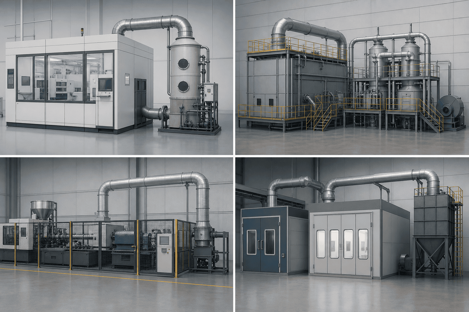
Consider a compounding line running PVC window profile and a recycled-content PS blend out of the same screw, vented through one header to one proposed tower. Apply the three-question screen: the HCl from PVC processing at 160–200 °C is soluble and reactive, and above roughly 100 ppm it is a clear absorption fit; the styrene from the PS blend, at roughly 300 ppm water solubility, is a poorly soluble VOC that a packed tower removes at the 30–50% water-only level—not disposal grade; and the die-head fume is a condensable aerosol that absorption cannot dissolve at all (source: XICHENG plastics-extrusion guide).
| Stream in the header | Pollutant form | Assignment |
|---|---|---|
| PVC barrel vent | Soluble acid gas (HCl) | Caustic packed tower: absorb |
| PS blend vent | Poorly soluble VOC (styrene) | Carbon adsorber or oxidizer: separate route |
| Die-head fume | Condensable aerosol | Venturi prescrubber: capture first |
Checking the Choice with Numbers
Let’s walk the numbers once more to check the choice holds: the residence time in the packed section is roughly 0.5–1 s, enough for HCl hydrolysis but not for styrene transfer, and duct temperature near the 160–200 °C melt band confirms the quench stage is required before packing. The screen splits the single header into a two-stage answer: the venturi captures the fume, the caustic stage absorbs the HCl, and the styrene fraction routes to carbon or oxidation on a separate line. You can now see why the polymer list, not the tower catalog, decides the fit. The same pattern—classify each stream, split the train, and let the poorly soluble fraction go elsewhere—repeats on every mixed line in this library, and it is the same three-question screen that drives every row of the industrial exhaust treatment matrix.
Frequently Asked Questions
What happens to the scrubbing liquid and the pollutants it captures?
The blowdown carries the absorbed species and the salts they form, so the disposal path is part of the fit test, not an afterthought. A chemical wet scrubber only makes sense where the site can treat or lawfully discharge the blowdown stream; where that path does not exist, dry sorbent injection or filtration becomes the defensible alternative. The wastewater and reagent-disposal question belongs in the scrubber water treatment resource before the equipment decision is finalized.
Can I combine several small exhaust streams into one scrubber?
Only when the chemistries are compatible. Acid and ammonia streams must stay separate because mixing them forms solid salts in the duct; a stream carrying condensable fume needs a venturi stage that a gas-only tower does not have. Merge streams after classifying each one by form, never before. The worked example above shows the split-train logic applied to a real mixed header.
How should I track scrubber performance after startup?
The three operating signals are pressure drop across the packed section, recirculation liquid flow, and pH at the setpoint. A rising pressure drop at constant flow means packing or demister fouling; a drifting pH means reagent feed or probe drift. Those three readings, trended and checked against the design baseline, are what the compliance discussion in the industrial controls compliance guide treats as the ongoing evidence of control.
How do I evaluate a vendor’s removal-efficiency claim?
Ask what pollutant-solvent couple, what configuration, and what operating conditions the number was generated for. The same tower that absorbs HCl in the mid-90s of percent removes little styrene, and a claim without a stated inlet concentration and test method is not a design basis. Hand the vendor the eight-input data sheet and require efficiency quoted against your classified stream, not against a generic one.
Your Next Step: Send the Process Data, Get a Route for Industrial Exhaust Treatment
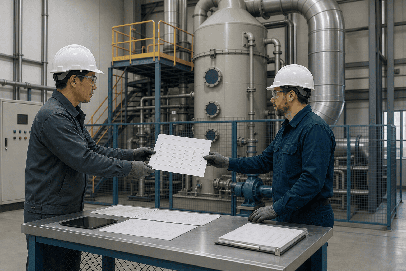
The route discussion ends where the data sheet begins. Before a supplier can size anything, use this checklist and gather the eight inputs the process rows depend on before you ask for a quote: flow rate, inlet temperature, pollutant list with forms, concentration bands, particulate load, moisture, capture arrangement, and wastewater or reagent disposal options. With that sheet, a vendor can route the stream to the right device family instead of quoting a tower that may not fit at all. That eight-input sheet closes the industrial exhaust treatment routing loop: classify the form, pick the device family, and send the data a supplier needs to price the route.
Send the completed process data to XICHENG for a route assessment and quotation inputs (request a quote), and open the owner guide for your process row in the matrix above to work the detailed method in parallel. Where the route confirms a chemical wet scrubbing duty for soluble acid gas, the chemical wet scrubber product family is the single product handoff for that route—and that closes the industrial exhaust treatment decision from matrix to quote.
*References: all factual numbers in this article are cited from XICHENG’s published guides (packed-bed semiconductor scrubber design, semiconductor exhaust treatment profile, glass manufacturing multi-stage wet scrubbing, plastics extrusion exhaust fit, automotive manufacturing air pollution control, cyanide electroplating LEV) and the EPA, OSHA, and NIOSH rules and factors those guides document (AP-42 Chapter 11.15; 40 CFR 60 Subpart CC; 40 CFR 63 Subpart SSSSSS; OSHA 1910.94; NIOSH IDLH documentation). No competitor efficiency claims are used. Vendor-published VOC absorption ranges are cited as vendor ranges, not guarantees.*


