
Key Takeaways
- A multi-stage wet scrubbing system for glass manufacturer exhaust is a route decision, not a type choice. Start by classifying the furnace load, then decide between wet scrubbing, dry sorbent injection, and filtration.
- The melting furnace drives the load. It contributes more than 99% of a glass plant’s particulate and gaseous emissions, with AP-42 uncontrolled factors near 0.7 kg/Mg particulate, 1.7 kg/Mg sulfur oxides, and 3.1 kg/Mg nitrogen oxides.
- Condensable material separates wet from dry. Glass furnace exhaust carries condensable sulfates and halides, which raises the temperature-management burden on filters and gives wet scrubbing its strongest fit.
- Regulation sets the target. 40 CFR 60 Subpart CC caps particulate emissions by glass segment and fuel, and the glass area-source NESHAP caps metal HAP at 0.01 g/kg, so the required efficiency is defined before equipment is chosen.
- A defensible selection ends in a data sheet. Eight inputs—flow, temperature, particulate, acid gas, metal HAP, condensables, materials, and wastewater—turn a route decision into an RFQ a supplier can price.
Choosing a multi-stage wet scrubbing system for glass manufacturer exhaust starts with a question that most scrubber pages skip: whether wet scrubbing is the right route for your furnace at all. Glass furnaces release a mixture unlike most industrial stacks—high-temperature gas carrying solid and condensable particulates, sulfur and halogen acid gases, and trace metal HAPs. The common mistake is to jump to a tower configuration before classifying that load. This guide walks the decision in order: what the furnace emits, what regulation requires, how to route the stream between wet scrubbing, dry control, and filtration, and which inputs a supplier needs to size a defensible multi-stage system.
What a Glass Furnace Emits: PM, SOx, HF, and Temperature
Before any scrubber can be sized, the load has to be classified by pollutant form and temperature. Each pollutant class drives a different piece of the control train, and mistaking one for another produces mis-sized systems.
Furnace type, fuel, and batch determine the pollutant load
The melting furnace contributes more than 99% of the particulate and gaseous emissions from a glass plant, so the furnace—not the batch plant, not the forming line—sets the control requirement. Continuous regenerative furnaces, the workhorse of container and flat glass, typically melt 45 to 272 Mg/day (50 to 300 tons per day), and capacity correlates with flue-gas volume and emission mass.
Sulfur oxides come from two paths: sulfur in the fuel and decomposition of sulfate fining agents such as sodium sulfate in the batch. A natural-gas-fired furnace with low-sulfate batch releases far less SOx than an oil-fired furnace or one running a high-sulfate recipe. Nitrogen oxides are thermal—they form at melting temperature (roughly 1,450 to 1,550°C for soda-lime glass), which is why low-NOx firing and post-furnace reduction, not gas cleaning, are the tools that control NOx. Fluoride shows up as HF when the batch contains fluorine compounds or when a coating line applies halogen chemistry downstream.
Condensable particulates are the distinguishing factor
Glass furnace particulate is not just solid ash. A meaningful share forms in the gas phase—volatilized sulfates, halides, and alkali compounds that condense as the gas cools. That condensable fraction changes the control comparison: a baghouse or electrostatic precipitator collects solid particulate efficiently, but condensable material re-nucleates downstream of the filter unless the gas is held at the right temperature through the whole envelope. This is the single largest difference between glass furnace exhaust and a simple dust stream, and it is why temperature control is part of the control-system decision, not a sidebar.
Wet scrubbing handles the condensable class directly. Quenching the gas and contacting it with liquid condenses the vapor species into the liquor where they can be absorbed or settled, which is why vendors position multi-stage wet systems for glass applications that combine particulate, condensable, and acid-gas load.
Why inlet temperature and moisture matter before any scrubber
Temperature decides what equipment is even allowed. Gas leaving a regenerative furnace after the checker chamber typically sits in the roughly 250 to 500°C (480 to 930°F) range, depending on furnace type, fuel, and how much heat recovery the plant runs. If the gas stays above about 600°F at the scrubber inlet, a quench stage must evaporatively cool it to near saturation (about 180°F) so the FRP or thermoplastic construction survives; above that boundary, metal or high-alloy construction, or heat recovery ahead of the scrubber, becomes part of the design. The same temperature question determines whether a dry filter is feasible at all, because fabric media corrode when the gas carries acid and the temperature management is poor.
Decision point: after this module you can list your furnace’s pollutant classes—solid particulate, condensable material, SOx, HF, metal HAP—and its approximate inlet temperature band, which is the input everything downstream depends on.
Compliance Targets: Official Factors and the Limits That Define Them
The second step is setting the target. Control equipment is selected against a required efficiency from two federal layers plus state permits: EPA factors describe the uncontrolled load, NSPS Subpart CC caps particulate by segment and fuel, and the area-source NESHAP caps metal HAP. These numbers, not vendor claims, define how many stages and how much packing you need.
What the AP-42 factors say about uncontrolled glass furnace emissions
EPA’s AP-42 Chapter 11.15 gives the uncontrolled factors used to estimate glass furnace load. Table 11.15-1 lists particulate at 0.7 kg/Mg (0.4 to 0.9 range), sulfur oxides at 1.7 kg/Mg (1.0 to 2.4), and nitrogen oxides at 3.1 kg/Mg (1.6 to 4.5) of glass produced. The same table documents what control devices achieve on glass furnaces: a low-energy scrubber reduces particulate and SOx by roughly 52% with no measured NOx effect, a venturi scrubber brings particulate below 0.1 kg/Mg, an electrostatic precipitator reaches up to 99% particulate collection, and a baghouse reaches about 99% where fabric corrosion is managed with tight temperature control.
These baselines calibrate vendor claims: EPA documents single-stage low-energy towers at roughly 52% removal on glass furnaces, outside the range that meets glass furnace compliance on its own.
NSPS Subpart CC: particulate limits by glass segment and fuel
40 CFR Part 60 Subpart CC is the federal NSPS for glass manufacturing plants, and it regulates particulate matter from melting furnaces, expressed in grams of particulate per kilogram of glass produced. The limit depends on the industry segment and the fuel. EPA’s Table CC-1 sets container glass at 0.1 g/kg on gas and 0.13 g/kg on oil; pressed and blown borosilicate at 0.5 and 0.65; pressed and blown soda-lime and lead at 0.1 and 0.13; pressed and blown recipes including opal and fluoride at 0.25 and 0.325; wool fiberglass at 0.25 and 0.325; and flat glass at 0.225 for both fuels. Mixed firing uses a heating-value-weighted standard.
The segment breakdown is itself a design input. The borosilicate allowance is five times the container-glass limit because the melt chemistry and throughput differ; a system that comfortably meets one segment’s target may miss another’s, so the limit you design against is segment-specific, not a single industry number.
The glass area-source NESHAP: metal HAP and the PM surrogate
For facilities that are area sources of hazardous air pollutants, 40 CFR Part 63 Subpart SSSSSS applies to continuous furnaces producing at least 45 Mg/yr (50 tons per year) per furnace from batch that includes compounds of arsenic, cadmium, chromium, manganese, lead, or nickel. The rule sets a 3-hour block average production-based limit: particulate at or below 0.1 g/kg of glass, or metal HAP at or below 0.01 g/kg, demonstrated with Methods 5 or 17. Particulate acts as the surrogate for metal HAP, which is why a PM measurement is the compliance test.
The practical effect is that facilities in the metal-HAP class need control that holds PM below the surrogate limit continuously, which pulls the design toward higher-efficiency trains—multi-stage wet scrubbing or dry sorbent injection plus a filter—instead of a single low-energy tower.
What stays in the permit: SO2, HF, and state requirements
Federal NSPS and NESHAP rules cover particulate and metal HAP, but sulfur dioxide, hydrogen fluoride, and other acid gases are controlled through state implementation plans and operating permits. There is no single federal number to quote for glass furnace SO2 or HF; the applicable limit is the one written into your Title V or state permit, set by the local authority on the basis of modeled and tested emissions. This guide gives the load-classification method and the equipment comparison; the specific SO2 and HF target is the permit question to confirm with your facility’s environmental staff before a supplier quotes.
Decision point: after this module you can state your compliance target—which NSPS segment and fuel columns apply, whether the metal-HAP NESHAP triggers, and which acid-gas limits sit in the permit—and you can translate that target into a required collection efficiency for the control train.
Route Selection: When Wet Scrubbing Beats Dry Control and Filtration
Once the load and the limit are classified, the next decision is the route: wet scrubbing, dry sorbent injection plus a filter, or filtration alone. The wet route is not the default—dry DeSOx and DeNOx systems downstream of electrostatic precipitators are common on large flat-glass lines. The route test compares each control class against the pollutant mix and temperature from the first two modules.
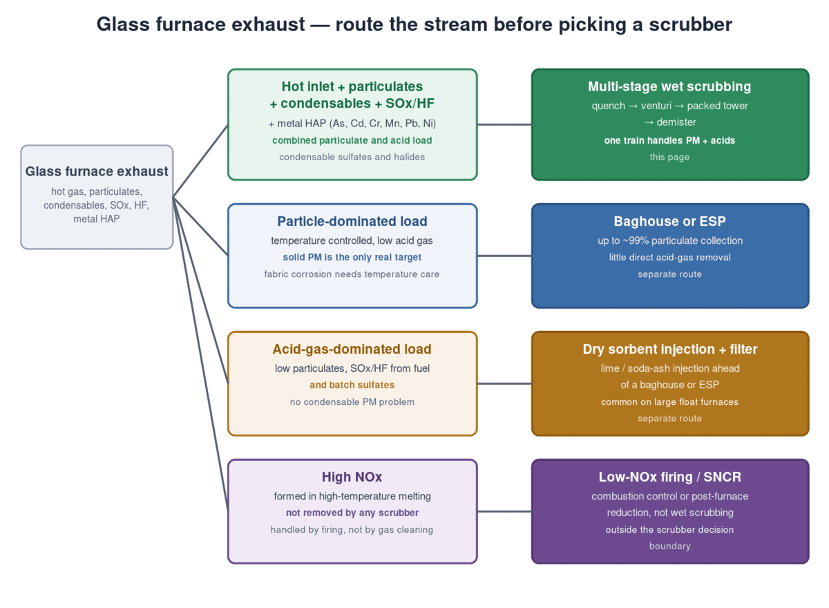
*Route the stream before picking a scrubber: the load and its temperature decide which control class can meet the limit.*
When wet scrubbing is the right route
A multi-stage wet system earns the job when the stream carries two or more pollutant classes at once. The strongest fit is a hot inlet (roughly 250 to 500°C) with solid and condensable particulate, acid gas from fuel or batch sulfates, and a metal-HAP trigger under the area-source NESHAP—the combination filters struggle to hold in one envelope. Vendor-documented glass applications support this: Monroe Environmental reports a multi-stage system on a glass furnace halide application achieving about 99.5% removal of fluorides and other halogen compounds.
The route also wins where condensables dominate: because the gas is quenched to near saturation and contacted with liquid, there is no dry filter envelope to hold above the acid dew point and no re-nucleation of condensed sulfates downstream of the media.
When dry sorbent injection or a baghouse fits better
Dry routes lead when the problem is mostly one thing. On large float lines, the mainstream configuration is dry scrubbing: lime or sodium sorbent injected into the duct, reacted, then collected on a baghouse or ESP, sometimes with a selective catalytic reduction step for NOx. GEA, a major glass-line supplier, documents dry DeSOx and DeNOx packages with roughly 140+ installations, dust outlet concentrations below 10 mg/Nm³, and typical furnace capacities of 600 to 1,000 tons per day—the scale at which dry reagent handling and multi-step trains become cost-effective.
A baghouse or ESP alone fits only when solid particulate is the sole target and acid gas is low, because neither device removes gaseous SO2 or HF directly. EPA’s AP-42 documents baghouse and ESP collection of about 99% on glass furnaces, but both depend on temperature management: fabric media corrode under acid load, and condensable material still needs an envelope held above its condensation point. With meaningful acid gas and condensables, dry sorbent plus a filter handles it; a bare filter does not.
The route test
Three questions separate the routes. First, does the stream carry condensable particulate or halogen acid gas? If yes, wet scrubbing (or dry sorbent injection, which reacts acid gas on the sorbent surface) is required—a bare filter cannot meet a 0.1 g/kg PM limit when vapor-phase material condenses after the media. Second, is acid gas a minor fraction of the load? If solid PM dominates and acid gas is negligible, a baghouse or ESP may meet the permit at lower operating cost. Third, does the metal-HAP NESHAP trigger apply? If batch contains arsenic, cadmium, chromium, manganese, lead, or nickel compounds and the furnace exceeds 45 Mg/yr, the PM surrogate limit of 0.1 g/kg pulls the design toward a high-efficiency train.
The table below compares each route against the pollutant classes from module one. No route removes NOx, which is handled at the firing level.
| Pollutant class | Multi-stage wet scrubber | Dry sorbent + baghouse/ESP | Baghouse or ESP alone |
|---|---|---|---|
| Solid particulate | Collects with venturi stage | Collects on fabric/plate | Collects (~99% per AP-42) |
| Condensable sulfates/halides | Quench condenses into liquor | Partial: sorbent surface reaction | Weak: re-nucleates downstream |
| SOx / HF acid gas | Packed-tower absorption | Sorbent reaction | None directly |
| Metal HAP | Collected with PM; PM acts as surrogate | Collected with PM | Collected with PM |
| NOx | None | None (separate SCR step) | None |
| Typical inlet temperature | 250–500°C, quench to ~180°F | 200–450°C, filter media limits | 150–260°C fabric limits |
The NOx boundary
No scrubber removes NOx, wet or dry. Nitrogen oxides form thermally at melting temperature (1,450 to 1,550°C for soda-lime), so the control tools are low-NOx firing, combustion staging, and post-furnace reduction such as SNCR or SCR—gas cleaning is outside the boundary of the scrubber decision. Design the control train around that: a scrubber that meets the PM and acid-gas limits still leaves a separate NOx compliance path to plan.
Decision point: after this module you can state which route your furnace load selects—wet multi-stage scrubbing, dry sorbent injection plus a filter, or filtration alone—and you know that none of them touches NOx. The rest of this guide assumes the wet route is selected.
Anatomy of a Multi-Stage Wet Scrubbing System for Glass Manufacturer Exhaust
A multi-stage wet scrubbing system for a glass manufacturer is not one device; it is a train of four sections, each removing one class of pollutant. For what wet scrubbers do at a basic level, see what scrubbers do for industrial air pollution; this page assumes that baseline and applies it to glass furnace exhaust. Quench protects downstream materials, the venturi takes fine particulate and condensables, the packed tower absorbs acid gas, and the demister keeps liquor out of the stack. Suppliers design the stages together because the gas condition leaving one section is the inlet condition of the next.
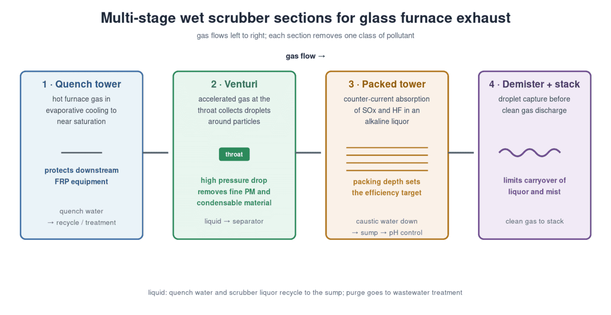
*Gas flows left to right; each section removes one pollutant class, and the liquor loop ties the stages together.*
Quench stage: protect the materials first
The quench is the temperature-management stage. Glass furnace gas above roughly 600°F at the scrubber inlet is evaporatively cooled to near saturation (about 180°F) by direct contact with recirculated water, which protects downstream FRP and thermoplastic construction from heat damage. Envigaurd, a scrubber manufacturer, documents this sequence for hot inlets: quench to saturation before the gas reaches the packed section, with the quench liquor recirculated and purged to treatment. The quench also condenses a share of the vapor-phase sulfates and halides into the liquor—the first pass at the condensable class.
Venturi stage: fine particulate and condensables
The venturi removes particulate, including the condensable material that survives the quench. Gas accelerates through a throat where injected water breaks into droplets that collide with particles; the pressure drop across the throat is the main efficiency variable, typically measured in inches of water column. EPA’s AP-42 documents a venturi scrubber on glass furnaces bringing particulate below 0.1 kg/Mg of glass produced, and the venturi is the section that carries fine PM collection in a wet train. High pressure drop is the trade: more collection, more fan energy.
Packed tower stage: acid-gas absorption
The packed tower is where SOx and HF leave the gas. Gas rises counter-current to recirculated alkaline liquor over random or structured packing, and the packing depth sets the acid-gas removal efficiency. Viron, a wet scrubber manufacturer, publishes the standard relationship for packed towers: roughly 24 inches of packing gives about 95% acid-gas removal and 48 inches about 99%, before accounting for reagent strength and liquid rate. On glass furnace exhaust, the tower design target comes from the permit limit and the inlet load—a facility facing a tight SO2 limit on an oil-fired, high-sulfate batch runs deeper packing and a stronger alkali loop than a gas-fired low-sulfate line. The packing and media logic for acid-gas service is worked through for a different industry in our semiconductor acid-gas packed-bed scrubber guide; here the quench and condensable load ahead of the tower change the sizing, not the absorption principle.
Demister and stack: keep the liquor inside
The final section captures entrained droplets before clean gas reaches the stack. A demister or mist eliminator removes liquor carryover, which otherwise becomes visible stack mist and loses reagent as drift. This section does not add removal; it protects the stack and the compliance measurement. Good demisting matters on glass furnaces because the gas is fully saturated and the liquor carries dissolved salts and solids that would deposit on stack surfaces if carried over.
Efficiency claims versus official baselines
Efficiency is a relative number, and a vendor’s percentage only means something against the inlet load it assumes. The way to read a claim is to convert it to an absolute outlet value and compare that against the permit limit. An illustrative check against EPA’s AP-42 uncontrolled particulate factor of 0.7 kg/Mg for glass furnaces shows the arithmetic: a single low-energy tower at the roughly 52% particulate removal EPA documents on glass furnaces leaves about 0.34 g/kg of glass produced—above the 0.1 g/kg container-glass NSPS limit—while a 99% claim on the same 0.7 kg/Mg inlet leaves about 0.007 g/kg.
That is why a claim of “99% removal” needs three answers before it is useful: the inlet concentration it assumes, the pollutant it measures, and the test method behind it. EPA’s AP-42 documents a venturi scrubber reaching below 0.1 kg/Mg of glass on particulate, the same order as the container-glass limit; vendor numbers above that should be read as device-class potential, not a guarantee at your inlet load. The permit limit, not the brochure, sets how much packing and what pressure drop the train needs.
Decision point: after this module you can determine how a vendor proposal maps each major component to a pollutant class—quench to temperature and condensables, venturi to PM, packed tower to acid gas, demister to carryover—and you can flag any efficiency claim that outruns EPA’s official baselines before it becomes a design input.
The Eight Inputs a Supplier Needs to Size the System
The route decision and the compliance target come together in a data sheet. The stage-by-stage logic behind multi-stage scrubber selection in general is owned by its own guide; this page fixes it to glass furnace loads. A multi-stage wet scrubber is quoted from eight inputs, and each one maps to a specific sizing decision. Missing or approximate inputs are the main reason quotes come back over- or under-sized.
Flow and temperature set the shell
Flue-gas flow, in actual cubic feet per minute or cubic meters per hour at the inlet condition, sizes the vessel diameter, the quench load, and the fan. Inlet temperature and the acid dew point set the material and the quench duty: gas above about 600°F requires quench cooling to near saturation before FRP construction is allowed, and the quench water rate is calculated from the sensible heat of the gas. Give the supplier the flow at the real inlet temperature, not a converted dry basis, because the velocity through the tower is what drives diameter and pressure drop.
Pollutant loads set the internals
Particulate concentration and particle size distribution set the venturi design; acid gas load in mass per hour (or ppmv) at the tower inlet sets the packing depth and the reagent flow; metal HAP species determine whether the metal-HAP NESHAP and its PM surrogate apply; and the condensable fraction, when the supplier knows it exists, justifies the quench and settles where it condenses. EPA emission factors are the starting estimate for each class: 0.7 kg/Mg particulate, 1.7 kg/Mg sulfur oxides, and 3.1 kg/Mg nitrogen oxides of glass produced, with the furnace’s actual throughput converting factors into mass per hour.
Materials and wastewater set the support system
Materials selection follows the chemistry: fluoride and chloride in the gas attack glass-fiber and metal internals, so halogen-rich batch or coating loads push the design to thermoplastic or lined construction, while oil-fired high-sulfur loads raise acid dew-point corrosion risk in upstream ductwork. Wastewater is the eighth input and the one most often deferred. The scrubber liquor loop concentrates dissolved solids and reaction products, and the purge stream has to go somewhere—the bleed rate, its loading, and the permitted discharge path are part of the RFQ, not an afterthought.
What to put in the RFQ
A complete inquiry gives the supplier the eight inputs in one table: flow and temperature, particulate load and size, SOx and HF load, metal HAP species, condensable fraction, materials or corrosion constraints, and the wastewater path—plus the compliance limit the system must meet. Add the stack or duct location, the available utilities (water, power, reagent), and the space envelope. That one page is what separates a price from a defensible quotation.
Decision point: after this module you can assemble the eight-input data sheet your facility needs to collect before a supplier can size a multi-stage wet scrubbing system for your glass furnace exhaust.
Sizing Example: A Container Glass Furnace, Step by Step
The selection method becomes concrete with a worked example. The values below are illustrative and use EPA’s published emission factors with a stated furnace throughput; your facility’s own testing, permit, and stack data replace them before any quote.
Step 1: Build the load from AP-42 factors
Assume a natural-gas-fired continuous regenerative furnace producing 150 Mg/day (150,000 kg/day) of container glass—an “example” value in the mid-range of the 45 to 272 Mg/day band. Apply EPA AP-42 uncontrolled factors to estimate the daily load:
| Pollutant | AP-42 factor (kg/Mg) | Daily load at 150 Mg/day | Hourly load |
|---|---|---|---|
| Particulate | 0.7 | 105 kg/day | 4.4 kg/h |
| Sulfur oxides (as SO2) | 1.7 | 255 kg/day | 10.6 kg/h |
| Nitrogen oxides | 3.1 | 465 kg/day | 19.4 kg/h |
These are planning estimates from EPA’s Table 11.15-1, not a substitute for a stack test, and the actual numbers scale linearly with your real throughput.
Step 2: Convert the permit limit to a required efficiency
Container glass on gas under NSPS Subpart CC is limited to 0.1 g particulate per kg of glass produced. At 150 Mg/day, the allowable PM is 0.1 g/kg × 150,000 kg/day = 15 kg/day. Against an estimated 105 kg/day uncontrolled, the train must remove (105 − 15)/105 ≈ 86% of the particulate. EPA documents a venturi scrubber on glass furnaces reaching below 0.1 kg/Mg—under 15 kg/day at this size—so a venturi section alone can carry the PM side of this permit.
If the furnace is an area source with batch containing the listed metal HAP compounds, the NESHAP adds the same 0.1 g/kg PM ceiling with a different compliance testing program (Methods 5 or 17).
Step 3: Size the acid-gas removal
The same furnace emits an estimated 10.6 kg/h of SOx as SO2. Suppose the state operating permit requires a 90% SO2 reduction—an “example” limit, since the real number is written into your facility’s Title V or state permit. A packed tower at roughly 95% removal (about 24 inches of packing per vendor-published curves) clears 90% with margin; a tighter limit or higher inlet load moves the design to 48 inches or a stronger alkaline liquor loop, and the selection is confirmed against the actual inlet concentration measured by testing.
Step 4: Check the train against every class
Walk the four stages with the example load. The quench cools hot gas to near saturation and condenses a share of the sulfate and halide vapor; the venturi brings PM below the 0.1 kg/Mg band; the packed tower holds SOx at or under the permit reduction; the demister keeps liquor out of the stack. NOx at 19.4 kg/h is untouched by any of this and is handled by low-NOx firing or post-furnace reduction as a separate compliance path.
Case B: a halide-coated line
The same furnace changes character when a downstream coating line puts halogen chemistry in the mix. Assume the batch now carries fluorine compounds and the measured or permit HF load is substantial—the “example” condition that turns the train into a fluoride problem. Wet scrubbing’s condensable advantage shows up here: fluoride leaves the glass as HF and as vapor-phase sodium or potassium fluoride that condenses as the gas cools, and the quench pulls both into the liquor before the packed section. This is the Monroe Environmental case cited in the route module: about 99.5% removal of fluorides and other halogens, a specialty case a plain baghouse cannot serve because the material condenses after the filter envelope.
The selection changes in three concrete ways. Materials move up to fluoride-resistant construction for the wetted sections, since fluoride attacks glass-fiber and many metal internals. The packed tower gains depth or a dedicated caustic loop, because HF absorbs readily but the liquor chemistry has to hold the loading. And the wastewater input stops being optional: the concentrated fluoride liquor needs a discharge path and treatment, which becomes part of the permit conversation before the RFQ, not after.
How the recommendation changes if conditions change
Run the same furnace on heavy oil and the sulfur load rises with the fuel, pushing the packed tower deeper and the alkali loop stronger—the SO2 side grows while the PM side barely moves. At the 600 to 1,000 tons-per-day scale of a large flat-glass line, the industry’s mainstream answer is dry sorbent injection plus ESP with SCR for NOx, which is why the route test decides wet versus dry before any stage is specified. Cool the gas and hold the temperature envelope, and a dry route may meet the permit at lower operating cost; heat it above the material boundary without a quench, and no scrubber is buildable until the temperature problem is solved. The worked example is a method, not a fixed answer: each changed condition re-runs the same four steps.
Decision point: after this module you can run this arithmetic with your own throughput and limits—factors to mass, limit to efficiency, efficiency to packing and venturi—before the first supplier conversation, so the quote for a multi-stage wet scrubbing system for glass manufacturer exhaust arrives against numbers your facility already owns.
Frequently Asked Questions
Is a wet scrubber the standard control on glass furnaces? No. Large flat-glass lines commonly run dry sorbent injection with a baghouse or ESP, sometimes with SCR for NOx. Wet multi-stage scrubbing is the stronger fit for loads that combine particulate, condensable material, and acid gas in one hot stream—the mixed-glass, specialty, and high-fluoride cases—not a universal answer.
Which is cheaper, wet scrubbing or dry control? There is no single figure to quote. The comparison depends on gas volume, acid load, target efficiency, reagent cost, and wastewater handling: dry systems spend on reagent and filter media, wet systems on water, caustic or lime, and liquor treatment. The deciding factors are the pollutant mix and the specific permit, not a rule of thumb.
Does a wet scrubber remove NOx from glass furnace exhaust? No. NOx forms thermally at melting temperature, and gas cleaning does not touch it. Low-NOx firing and post-furnace reduction such as SNCR or SCR are the compliance tools.
What material should the scrubber be? The gas temperature and halogen load decide it. Gas quenched to near saturation allows FRP or thermoplastic construction; chloride- and fluoride-rich gas attacks fiberglass and metal internals, which pushes toward lined or specialty materials. Oil-fired, high-sulfur loads raise corrosion risk in the upstream ductwork.
How much removal is required? The required efficiency is the difference between the uncontrolled load and the permit limit, expressed as a percentage. NSPS Subpart CC and the area-source NESHAP give PM and metal-HAP ceilings in g/kg of glass produced; SO2 and HF targets come from your state permit. Compute that number before equipment selection, not after.
Conclusion: Specifying a Multi-Stage Wet Scrubbing System for Glass Manufacturer
Selecting a multi-stage wet scrubbing system for glass manufacturer exhaust is a route decision that ends in a data sheet. Classify the load the furnace emits—solid and condensable particulate, SOx, HF, metal HAP, and a 250 to 500°C temperature band; confirm the limit your segment, fuel, and permit impose; route the stream between wet scrubbing, dry sorbent injection, and filtration, remembering that no route removes NOx; then hand the supplier the eight inputs that turn the route into a priced system. The worked example shows the full conversion from factors to removal efficiency.
When the route selects wet scrubbing, the train to specify is the multi-stage combination covered here: quench, venturi, packed tower, and demister. XICHENG EP Ltd supplies industrial flue gas scrubbers and SOx wet scrubber systems for this kind of load; an inquiry that includes the eight-input data sheet gets a faster, better-grounded response. The decision process here, not any product, protects the sizing—and the compliance test that follows it.


