
Key Takeaways
- A packed bed scrubber to reduce acid gasses at semiconductor plant is a counter-current absorption tower that uses pH-controlled caustic water to remove HCl, HF and other acid gases from etch and wet-clean exhaust.
- Route by stream class, not by chemistry alone. Acid gases belong on the packed bed; solvent vapors, hydrides and fluorinated process gases route elsewhere and must not share the wet line.
- One packed bed does not treat every fab exhaust stream. Water absorption caps many solvents near 90%, silane-type hydrides are pyrophoric and dust-forming, and fluorinated process gases pass through caustic wash unreacted.
- HF drives material selection; HCl drives corrosion. HF service demands a glass-free PP line, while wet HCl rules out 304/316 stainless for wetted parts.
- Size on peak flow, verify on normal, and build redundancy into continuous service. Design the tower for peak load and run pH control at normal load.
- Hand your supplier a complete design input sheet. The twelve fields in this guide convert your stream data into a request a scrubber vendor can size from.
When a fab adds etch and wet-clean capacity, the exhaust from those tools stops being a routine ventilation problem and becomes a routing decision. The central question is which headers feed a packed bed scrubber to reduce acid gasses at semiconductor plant, and which route elsewhere. The most common mistake is assuming one scrubber treats every fab exhaust stream; in practice the decision starts with stream class, not chemistry. Acid gases absorb readily in caustic water; solvent vapors, hydrides and fluorinated process gases do not, and mixing them into one wet line creates salt deposits, aerosols and compliance risk. This guide covers the four-class routing decision, the HCl-versus-HF differences, the tower parameters, and the design input sheet to hand over.
Direct Answer: Which Semiconductor Exhaust Streams Belong on a Packed-Bed Scrubber?
A packed-bed scrubber is the fit control device for one stream class: acid gases from etch and wet-clean tools, including HCl, HF, sulfuric-acid mist and nitric-acid fumes. Solvent, hydride and fluorinated-process-gas streams need different treatment; mixing them into the acid-gas scrubber causes the failures at the end of this section. The routing logic is simple to state and hard to skip: classify each header before you size anything.
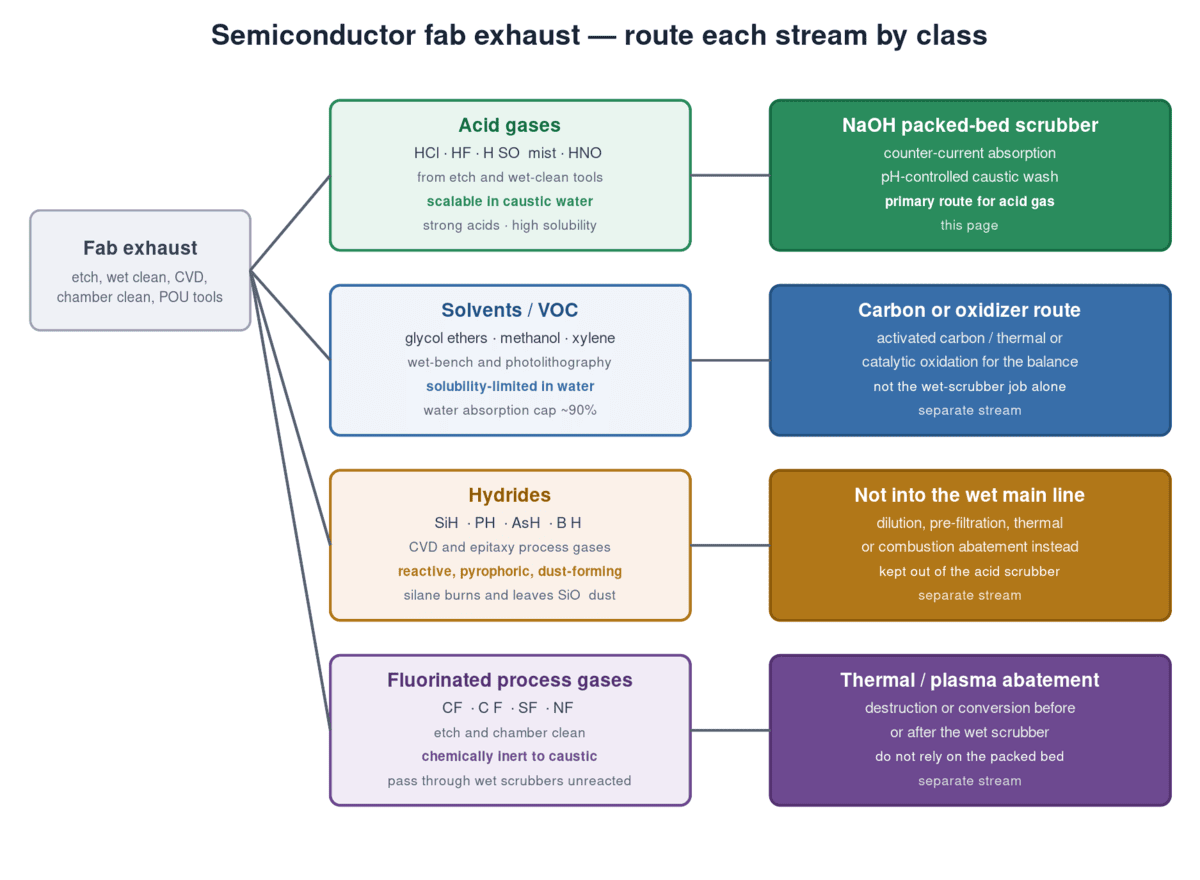
The four exhaust stream classes in a semiconductor plant
Semiconductor exhaust splits into four classes by how each class behaves in a wet scrubber. The table below is the routing map used throughout this guide.
| Stream class | Typical sources | Behavior in a wet scrubber | Route to |
|---|---|---|---|
| Acid gases — HCl, HF, H₂SO₄ mist, HNO₃ | Etch, wet clean, some chamber clean | High water solubility; neutralized by caustic | NaOH packed-bed scrubber (this guide) |
| Solvents / VOC — glycol ethers, methanol, xylene | Wet bench, photolithography, IPA use | Water absorption caps many VOCs near 90% | Carbon or thermal/catalytic oxidation for the balance |
| Hydrides — SiH₄, PH₃, AsH₃, B₂H₆ | CVD, epitaxy | Reactive and pyrophoric; silane dust fouls packing | Dilution, pre-filtration, thermal abatement |
| Fluorinated process gases — CF₄, C₂F₆, SF₆, NF₃ | Etch, chamber clean | Chemically inert to caustic; pass through unreacted | Thermal or plasma abatement, not the packed bed |
The official basis: five HAPs make up more than 90% of semiconductor HAP emissions
The federal anchor for this split is the Semiconductor Manufacturing NESHAP, 40 CFR Part 63 Subpart BBBBB. It identifies five chemicals that together account for more than 90% of the hazardous air pollutants emitted by semiconductor manufacturing: HCl, HF, glycol ethers, methanol and xylene. Only the first two are strong acid gases; the other three fall into the solvent class — so the acid-gas route and the solvent route both trace to the same official HAP inventory.
Why mixed streams break the scrubber
Acid-gas scrubbers fail when non-acid streams share the wet line. Three mechanisms dominate. Ammonia and HF form ammonium fluoride salt, NH₄F; keeping the product of ammonia and HF concentration below 100 ppm² at room temperature suppresses the reaction — which is why alkaline and acid headers are kept separate. Ammonia and HCl form ammonium chloride aerosol in the duct, a fine white salt that coats packing and defeats absorption. Silane (SiH₄) is pyrophoric above roughly 1.4% and is diluted below about 0.5% before exhaust; its combustion leaves SiO₂ dust that can plug packing within 4–8 weeks. Fluorinated gases such as CF₄ and SF₆ are chemically inert to caustic soda and pass through the bed unreacted.
For PFC destruction and silane-management detail, see the semiconductor exhaust treatment guide; this page handles the routing decision and the packed-bed design that follows it.
You can now classify each exhaust header in your fab as acid, solvent, hydride or fluorinated, and decide which streams may be routed to a packed-bed scrubber. The next section shows how the packed bed removes the acid stream — and the conditions under which it stops fitting.
How a Packed-Bed Scrubber Captures Acid Gases — and When It Fits
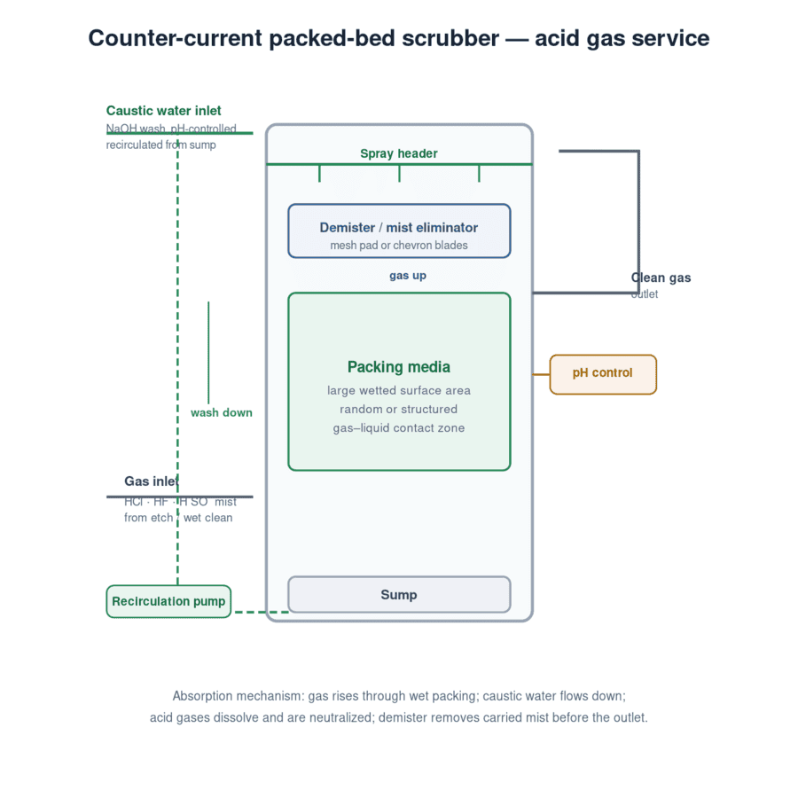
A packed-bed scrubber removes acid gases by counter-current absorption: the gas rises through wetted packing while caustic water flows down, and dissolved acid neutralizes on contact. The U.S. EPA classifies wet scrubbers for gaseous control as absorbers and reports that most achieve more than 90% removal of the target pollutant; the balance depends on pollutant solubility and on tower design.
Counter-current packed-tower mechanics
Gas enters below the packing and travels upward through the wetted bed; caustic water is sprayed above the packing and works downward, wetting the media and carrying dissolved acid to the sump. A demister above the bed removes mist carried by the gas before the clean-gas outlet. What a wet scrubber does at the system level is covered in our overview of industrial wet scrubbers; here the focus is the acid-gas tower and its design inputs.
Caustic chemistry: NaOH and pH control
Neutralization is the second stage of removal. Caustic soda raises the pH of the recirculating wash so absorbed acid is consumed rather than re-emitted. For strong acids such as HCl and HF, scrubber liquid pH is typically held at 7.5–9.5 with automatic caustic feed; pH is the primary process control on the tower.
Fit conditions and limits
The packed bed fits streams that are water-soluble, moderately concentrated and cool enough for polymer construction. When those conditions fail, the device changes.
| Fit condition | Favorable for the packed bed | Unfavorable — choose something else |
|---|---|---|
| Pollutant solubility in water | High (HCl, HF) | Low (many VOCs; water absorption caps near 90%) |
| Inlet temperature | At or below 60°C — protects plastics, raises solubility | Above 80–100°C — needs quench or FRP construction |
| Particulate load | Low; pre-washed gas | Silane dust or solids — pre-washer or cyclone first |
| Concentration | Moderate and continuous | Trace levels — carbon polishing; high heat release — quench |
You can now judge whether your acid stream fits a packed bed or needs upstream conditioning, and you know the two drivers, solubility and temperature, that decide it. The next section narrows the design by the acid chemistry itself.
HCl vs HF: How the Acid Chemistry Changes the Scrubber Design
The acid chemistry changes wetted materials and wastewater, not the absorption principle. HCl drives chloride pitting of stainless steel; HF attacks the silica in glass-reinforced materials and forces a glass-free line. You size the same counter-current tower for both acids; you do not specify the same materials.
HCl: fast absorption, chloride pitting
HCl is highly water-soluble and reacts quickly with caustic soda, so a packed bed achieves high removal in a compact tower. The design consequence is corrosion: chloride-ion pitting makes 304/316 stainless unsuitable for wet HCl service, and XICHENG does not recommend those grades for wetted parts. Packed-bed HCl removal in caustic media is listed above 98% under design conditions.
HF: silica attack, glass-free materials, fluoride wastewater
HF behaves differently because it attacks SiO₂, which rules out glass-fiber-reinforced plastic on any wetted surface — the glass fibers dissolve — and pushes the line to polypropylene with no glass reinforcement. Polypropylene rated to 80°C continuous service is the standard choice for HF headers and towers. Two consequences follow. First, SiF₄ hydrolysis can redeposit SiO₂ in downstream ducting, so duct material and layout matter, not just the tower. Second, fluoride ends up in the recirculating wash, and the wastewater stream needs fluoride treatment before discharge. Packed-bed HF removal in caustic media is listed above 95% under design conditions.
What stays the same — and the compliance boundary
Both acids use the same NaOH chemistry, the same pH band, the same counter-current structure and the same demisting rules. This guide covers design consequences; the emissions-limit comparison between HCl and HF scrubber systems across jurisdictions is a separate question handled in our acid fume scrubber systems compliance guide.
| Design dimension | HCl | HF |
|---|---|---|
| Absorption | High water solubility; fast caustic reaction | High solubility; moderate caustic reaction |
| Wetted materials | PP or FRP acceptable; 304/316 stainless not recommended | Glass-free PP; no FRP glass fiber in contact |
| Byproducts | Sodium chloride in the recirculating wash | Fluoride in wastewater; SiF₄ hydrolysis can deposit SiO₂ |
| Efficiency reference (design conditions, caustic media) | Above 98% | Above 95% |
| Wastewater | Simple neutral salt | Fluoride treatment required before discharge |
You can now lock the material rule for your acid mix — glass-free PP internals for HF, no 304/316 stainless on wet HCl — before any sizing begins. The next section turns to the flow, concentration and temperature basis the sizing starts from.
Design Basis: Normal and Peak Flow, Concentration and Temperature
Size the tower for the peak flow it will ever see, and control it at the normal flow. The design basis is six fields, and every downstream parameter in this guide draws on them.
Flow: normal, peak and turndown
Typical tool exhaust runs 200–2,000 cfm per chamber, and central systems gather many chambers, so sizes vary widely; XICHENG packed-bed scrubbers are built for 3,000–45,000 m3/h single-tower service. Design on the peak flow to size the tower diameter and fan, and control to the normal flow so the pH loop and caustic feed track real load.
Concentration: normal, peak and co-pollutants
The supplier needs normal and peak concentration for each acid, not a single average. Peaks come from tool changeover, batch wet-bench loads and chamber clean cycles. Co-pollutants matter as much as the acids: ammonia on the same header forces salt management, and solvent vapor changes the mass balance.
Temperature and gas conditions
Inlet temperature drives both material selection and solubility. XICHENG rates its acid-fume scrubber standard inlet at 60°C, the reinforced build at 80°C and FRP construction at 120°C. Cooler gas dissolves more acid and protects polymer internals, which is why a quench stage precedes the bed when the stream is hot.
| Design-basis field | What to record | Why it matters |
|---|---|---|
| Gas flow, normal | m3/h or cfm at average operation | Fan sizing, pH setpoint |
| Gas flow, peak | m3/h or cfm at worst case, with duration | Tower diameter, velocity check, fan capacity |
| Gas flow, minimum | m3/h at turndown | VFD range, low-flow protection |
| Inlet concentration, normal | ppm of each acid gas | Caustic dosing, mass-load basis |
| Inlet concentration, peak | ppm at changeover | Peak caustic demand, demister load |
| Inlet temperature | °C, normal and maximum | Material selection, quench need |
You can now fill the six fields of the design basis and decide what to size on versus what to control to. The next section turns that basis into the tower parameters.
Tower Design Parameters for a Packed Bed Scrubber to Reduce Acid Gasses at Semiconductor Plant: L/G, Gas Velocity, Pressure Drop and Packing
Four parameters define the tower: liquid-to-gas ratio, superficial gas velocity, pressure drop and packing. XICHENG engineers its packed-bed scrubbers at a typical L/G of 1.5–3.0 L/m³ and a pressure drop of 300–800 Pa, with gas velocities in the 1–3 m/s band.
Liquid-to-gas ratio and liquid rate
L/G sets the mass-transfer surface. The XICHENG packed-bed range is 1.5–3.0 L/m³; industry references also quote liquid rate per tower cross-section at 5–20 L/min·m². Either way the intent is the same: keep the packing fully wetted without flooding the bed.
Gas velocity and pressure drop
Superficial gas velocity balances residence time against entrainment. The common design band is 1–3 m/s: below it, mass transfer starves; above it, gas carries liquid up into the demister. Pressure drop across the packed bed lands at 300–800 Pa in typical acid-gas service and sets the fan duty. The EPA warns that flow outside the design window degrades removal and can drive aerosol condensation.
Packing selection
Packing is where area and fouling trade off. XICHENG offers six media types — multi-face hollow balls, Pall rings, structured packing, ceramic saddles, Tellerette and Tri-Packs — spanning a specific surface of 100–350 m²/m³. Smaller media add removal but raise pressure drop and trap fouling; larger media resist plugging at the cost of area. For silicon-dust or salt-forming service, the open media wins.
| Tower parameter | Typical range | Design role |
|---|---|---|
| L/G ratio | 1.5–3.0 L/m³ (XICHENG packed-bed) | Mass-transfer surface |
| Liquid rate | 5–20 L/min·m² cross-section (industry reference) | Distributor and nozzle design |
| Superficial gas velocity | 1–3 m/s | Residence time vs entrainment |
| Pressure drop | 300–800 Pa | Fan sizing, packing choice |
| Packing specific surface | 100–350 m²/m³ | Area vs fouling trade-off |
With these four parameters you can draft the tower and chemical design basis your supplier will size from, and you can flag any quoted L/G or velocity that sits outside the normal band. Materials are the next constraint to lock.
Materials and Temperature: PP, FRP and Stainless Boundaries for Acid Service
For semiconductor acid-gas service, polypropylene is the standard wetted material to 80°C continuous, FRP extends temperature to roughly 104–120°C, and 304/316 stainless is not recommended on wet HCl. Temperature is the first gate; acid chemistry is the second.
The material decision table
Material choice follows two questions: how hot is the gas, and which acids are in it?
| Material | Temperature limit | Acid-service notes |
|---|---|---|
| PP (standard) | 80°C continuous, 100°C short-term | Glass-free, HF-compatible; not for strong oxidizing acids above 50°C or aromatic solvents |
| PP (thickened / reinforced) | 80°C | Standard acid-fume inlet 60°C, reinforced build 80°C |
| FRP | ~104–120°C | Handles higher temperature; glass fibers attacked by HF — not for HF contact |
| SS304/316 | Not rated for wet acid service | Not recommended for wet HCl (chloride pitting) |
Temperature management
When inlet temperature exceeds the polymer limit, the standard fix is an evaporative quench or pre-cool stage ahead of the bed. The same stage protects plastics and raises acid solubility. Sulfuric-acid mist must be quenched below its acid dew point, about 120°C at 93% H₂SO₄, or it condenses on internals and re-entrains.
The HF material rule
The HF rule overrides generic tables: no glass-fiber reinforcement may contact the acid. That means a PP tower and PP duct for HF service, not FRP. XICHENG’s standard PP shell is 8–12 mm, and the material set is confirmed with the supplier against the actual acid mix and temperature.
You can now specify the wetted-material package for your acid mix and temperature, and decide whether an upstream quench is required before the tower. The next section covers the mist and aerosol that a packed bed can otherwise let through.
Demisting and Aerosol Control: Condensation, Mist and Plume
Acid-gas scrubbing is two-phase. The gaseous acid absorbs in the packing, but sub-micron acid mist can pass through a packed bed; without a high-efficiency demister, 20–40% of that mist can leave with the gas. A two-stage demister, mesh pad plus chevron blades, closes the gap and suppresses a visible plume.
Sub-micron mist and the two-stage demister
XICHENG’s acid-fume scrubber data quantifies the failure mode: without an outlet demister, a packed bed may pass 20–40% of sub-micron acid mist. The fix is two-stage separation, a PP mesh pad ahead of chevron blades, which removes the carried mist and cuts plume visibility. Efficiency references in caustic media run above 98% for HCl, above 95% for HF and for H₂SO₄ mist, and above 90% for HNO₃.
Sulfuric-acid mist: quench below the dew point
Sulfuric mist does not absorb until the gas is cooled below the acid dew point; a quench stage ahead of the bed cools the stream to polymer-safe temperatures and puts the mist into a condition the packing can absorb.
Salt aerosols and the plume
The plume problem is usually a chemistry problem upstream. Acid and ammonia mixed in one header form ammonium salts, NH₄F and NH₄Cl, as sub-micron aerosol that no demister fully captures; the EPA lists aerosol condensation as a primary wet-scrubber operating problem. Segregate the acid and alkaline headers and most salt aerosol disappears.
| Aerosol risk | Mechanism | Control |
|---|---|---|
| Sub-micron acid mist | Passes the packed bed with the gas | Two-stage demister (mesh + chevron) |
| H₂SO₄ mist | Condenses below the acid dew point | Quench before the bed |
| Salt aerosol (NH₄F, NH₄Cl) | Acid plus ammonia mixing | Segregate acid and alkaline streams |
For a heavy two-phase acid-mist load, an acid fume scrubber with two-stage demisting is the adjacent configuration; the packed-bed design here carries the same demisting rule.
You can now specify the demisting grade and quench requirement for your stream, and decide whether the two-phase acid-fume configuration fits your mist load. The next section covers the redundancy a continuous fab line forces on the design.
Redundancy and Continuous Operation: How Much Backup Does a Fab Scrubber Need?
Redundancy is driven by the consequence of an unscheduled stop, not by habit. A 24/7 fab where a scrubber outage trips tool sets and risks a permit excursion needs redundant fans, pumps and dampers; a batch line may not.
When continuous operation drives redundancy
Monroe Environmental’s 30,000 cfm semiconductor packed-bed case ran continuously and carried redundant fans, automatic dampers and redundant recirculation pumps — the equipment set a 24/7 fab forces. An outage on a wet bench means idle tools, lost production and a permit event if exhaust bypasses treatment.
The redundancy decision framework
The decision is a consequence-weighted choice, not a checklist item.
| Operation pattern | Suggested redundancy |
|---|---|
| 24/7 continuous; outage trips tools | N+1 fan, N+1 recirculation pump, redundant dampers, service bypass |
| Batch or daylight operation | Single fan, spare pump, maintenance bypass |
| Point-of-use on critical tools | Per-tool or shared spare; SEMI S2-rated units |
A maintenance bypass keeps the scrubber serviceable without stopping the line; a dual-tower configuration is the next step when even a brief bypass is unacceptable. Point-of-use wet scrubbing moves abatement to the tool itself, at 1,000–4,000 m3/h per unit with ±10 Pa pressure stability under variable-frequency control.
Turndown: VFD fans and pumps
Redundancy complements turndown, not the reverse. Variable-frequency drives on the fan and recirculation pump match the peak-to-normal flow spread from the design basis, and the pH loop holds the wash at 7.5–9.5 as the load varies.
You can now decide the redundancy level for your operation by weighing outage consequence against installed cost, and name the bypass and spare components for your spec. The next section covers the monitoring and maintenance plan and where the system boundary sits.
Monitoring, Maintenance and the System Boundary
Keep a fab scrubber in compliance with four measurements — pH, pressure drop, liquid flow and recirculation rate — plus a maintenance schedule that removes fouling before it degrades removal. The more than 90% removal a wet absorber is designed to deliver holds only while pH, liquid flow and pressure differential stay in range. The system also ends somewhere: wastewater, duct, fan and controls are part of the design scope.
What to monitor
The EPA names pressure differential, liquid flow and scrubber-liquid outlet concentration as the primary wet-scrubber performance indicators, with gas flow, neutralizing feed rate and outlet temperature as secondary, and pH, specific gravity or makeup rates as acceptable substitutes. A practical cadence is weekly pH checks, monthly pressure-drop and packing-distribution checks, and an annual open-hatch inspection of packing, demister and nozzles.
Fouling, nozzles and packing service
Fab fouling is mostly salt and silicon. Mineral scale, silicon dust, photoresist mist and neutralization sludge accumulate on packing, raise pressure drop and cut removal. Large-bore spiral nozzles with a 6–8 mm minimum channel resist salt plugging, and an automatic water flush on shutdown clears the headers. Packing replacement is a service recommendation, commonly every two years in fab service, not a regulatory interval; the pressure-drop trend tells you when it is due. One maintenance provider estimates hundreds of dollars per year in added fan energy for every 0.1 in. w.c. of extra pressure drop.
The system boundary: wastewater, duct, fan, controls
Wet scrubbing transfers the pollutant to the liquid phase, so the wastewater destination is a design input, not an afterthought. The fan is sized from the 300–800 Pa bed pressure drop plus duct losses, and for HF service the duct is PP. Controls close the loop: pH, level and pressure-drop instruments feed the caustic dosing pump and the alarms.
| Monitoring parameter | Cadence | What it signals |
|---|---|---|
| Wash pH | Weekly (continuous preferred) | Neutralizer health, acid-load change |
| Pressure drop across bed | Monthly | Fouling, channeling, packing condition |
| Liquid flow / recirculation | Monthly | Pump wear, nozzle plugging |
| Open-hatch inspection | Annual | Packing, demister, nozzle condition |
You can now plan the monitoring schedule and define the full system boundary — wastewater destination, duct and fan, and controls — before you hand the spec to a vendor. The worked example in the next section runs the whole chain and produces the sheet you hand over.
Worked Example: Routing and Sizing a Packed Bed Scrubber to Reduce Acid Gasses at Semiconductor Plant
Run the whole chain on a concrete case, then turn the result into the twelve-field design input sheet. All figures in this example are illustrative.
The scenario and the decision chain
Consider a wet-clean and etch bay with one combined acid header. The recorded inputs are: normal flow 8,000 m3/h and peak flow 12,000 m3/h (example); HCl at 25 ppm normal and 60 ppm peak; HF at 10 ppm normal and 25 ppm peak; inlet temperature 45°C; a separate ammonia header; continuous 24/7 operation.
- Routing: the header is HCl plus HF, with no ammonia, solvent, hydride or PFC — the acid-gas class, so it belongs on the packed bed. The ammonia header stays separate, removing the salt-aerosol risk.
- Fit and chemistry: high solubility at 45°C, well under the 60°C standard inlet limit, so no quench is required. HF is present, so the wetted line is glass-free PP; no 304/316 stainless on the wet HCl.
- Tower: size on the peak 12,000 m3/h. At an L/G of 1.5–3.0 L/m³, recirculation flow is roughly 18,000–36,000 L/h (example). Gas velocity is checked against the 1–3 m/s band and pressure drop budgeted at 300–800 Pa.
- Demisting: two-stage demister, mesh plus chevron, for the sub-micron mist an HF/HCl header carries.
- Redundancy: 24/7 operation, so N+1 fan, N+1 recirculation pump and a service bypass.
- Monitoring: weekly pH, monthly pressure drop, annual open-hatch inspection.
The twelve-field design input sheet: the checklist to send with your RFQ
The same chain compresses into the request your supplier sizes from.
| # | Field | What you provide |
|---|---|---|
| 1 | Exhaust constituents | Each acid gas with concentration range |
| 2 | Flow, normal | m3/h |
| 3 | Flow, peak | m3/h and duration |
| 4 | Flow, minimum | m3/h at turndown |
| 5 | Inlet temperature | °C, normal and maximum |
| 6 | Humidity and particulates | % RH, dust load |
| 7 | pH control range | Target band, for example 7.5–9.5 |
| 8 | L/G and pressure-drop budget | Preferred L/G, allowable Pa |
| 9 | Wetted material preference | PP, FRP, or other |
| 10 | Demisting grade | Two-stage or single |
| 11 | Redundancy and bypass | N+1 fans/pumps, bypass |
| 12 | Wastewater destination | Plant treatment or discharge limits |
How the outcome changes with conditions
The design is only as good as the inputs, and it moves with them. Inlet temperature above 80°C forces FRP construction or a quench stage. Silicon dust on the header adds a pre-washer or cyclone before the bed. A solvent-heavy header stays off the packed bed and routes to carbon or oxidation, as the routing table directed.
Run the same sequence on your own headers — classify each stream, confirm the packed bed fits the acid gas, then size on peak flow and hand the supplier the twelve fields above. That is the complete job of a packed bed scrubber to reduce acid gasses at semiconductor plant: route the acid stream, size the tower, and leave nothing for the vendor to guess. With the sheet assembled, you can decide your next step — send it to a packed-bed scrubber supplier or run the routing on the next header.
FAQ: Packed-Bed Scrubbers for Semiconductor Acid-Gas Exhaust
Can one packed-bed scrubber handle all semiconductor exhaust?
No. The packed bed fits the acid-gas class only. Solvent vapors exceed water absorption near 90%, hydrides are pyrophoric and dust-forming, and fluorinated process gases pass through caustic wash unreacted. Mixing classes creates salt deposits and aerosols.
Packed-bed scrubber vs point-of-use abatement: which for acid gases?
Both are defensible; the choice is architectural. A central packed bed gathers many tool headers under one maintenance team; point-of-use abatement moves scrubbing to the tool with shorter duct runs and less clean-room air loss, at roughly 1,000–4,000 m3/h per unit. Choose central when many headers already converge; choose point-of-use when tool layout favors local abatement.
How often does packing need cleaning or replacement in fab service?
Fab service commonly replaces or deep-cleans packing about every two years, driven by salt and silicon fouling, but the pressure-drop trend is the real trigger. When pressure drop rises above the design budget and flushing does not restore it, the packing is due.
What is the difference between an HCl scrubber and an HF scrubber?
The tower is the same counter-current caustic design; the differences are materials and wastewater. HCl forces the stainless rule, no 304/316 on wet chloride, and produces a simple neutral salt; HF forces a glass-free PP line and a fluoride wastewater stream that needs treatment before discharge.
Conclusion: Specifying a Packed-Bed Scrubber for Semiconductor Acid-Gas Exhaust
A packed bed scrubber to reduce acid gasses at semiconductor plant is the right device for the acid-gas stream class, sized on peak flow and built around the chemistry: glass-free PP for HF, no 304/316 stainless on wet HCl, two-stage demisting, and redundancy where the line cannot stop. The four-class routing table and the twelve-field design input sheet are the two artifacts to carry from this guide.
Review My Fab Exhaust Streams
To review a packed-bed scrubber for semiconductor acid-gas exhaust, provide the exhaust constituents with normal and peak concentration, normal and peak flow, inlet temperature, the pH control range you can operate, the pressure-drop budget, your wetted-material preference, demisting and redundancy requirements, and the wastewater destination. XICHENG can use these inputs to recommend the appropriate packed-bed configuration and flag the fan, duct and control information that still needs confirmation.
Review the packed-bed scrubber product range and send your header data to start the review.


