
Many wet-scrubber projects stall because teams mix decisions from different stages. A supplier is asked for a quote before the gas data are ready, or a rebuild is discussed before anyone checks the operating baseline. This wet scrubber project lifecycle map shows where your project is now, what decision belongs there, and which focused resource should come next.
Key Takeaways
- Name your stage first. A wet scrubber project lifecycle is the sequence of decisions from selection through installation, operation, rebuild, facility planning, and delivery.
- Use one guide for each decision. The matrix sends each stage to the focused guide that handles it in depth.
- Start with the gas stream. Confirm the control approach and collect the operating inputs before equipment is specified.
- Diagnose before rebuilding. Underperformance is a gas-liquid system symptom until measured evidence proves otherwise.
- Prepare the RFQ inputs first. A complete data package makes the supplier conversation specific and comparable.
The Wet Scrubber Project Lifecycle: Six Decision Stages
A wet scrubber project lifecycle is not a straight purchasing sequence. It is a chain of six decisions: confirm the control approach, install and commission it, operate against a baseline, diagnose degradation, plan the surrounding facility, and package the next scope for delivery. A team can enter the chain at any point, but the evidence from one stage must feed the next.
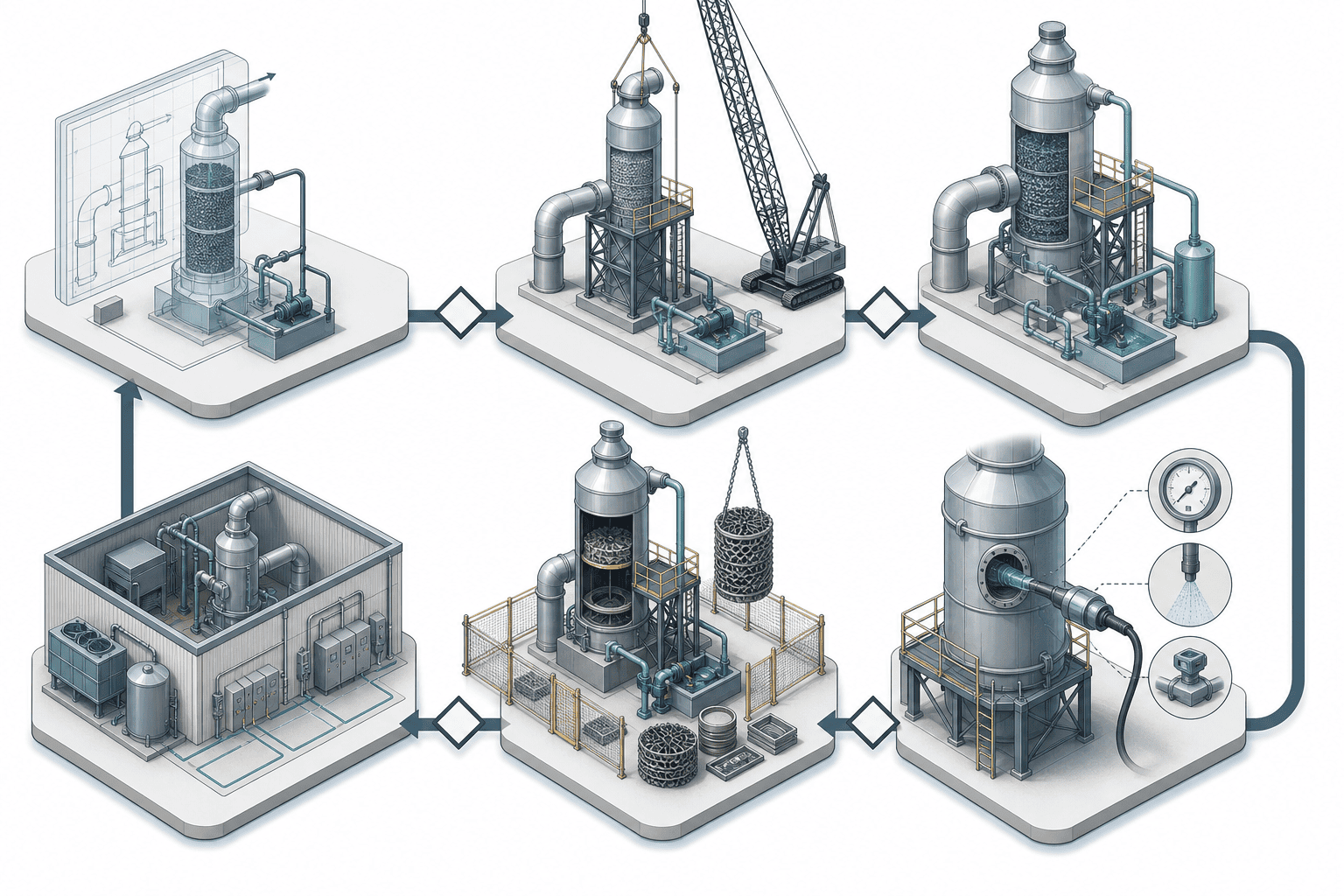
How this resource works
Start with the matrix below and choose the row that describes the decision in front of you—not the equipment age or the department asking the question. A new 10,000 cfm project belongs in selection even if a vendor has already proposed a vessel. A running system with a 300 gpm circulation loop belongs in operation when its readings drift, not in replacement simply because it has been in service for years.
Each row points to the focused guide that carries the detailed method. The lifecycle map gives enough context to choose a route, then stops before it repeats the installation checklist, fault table, rebuild assessment, or room-design data sheet. Your output from this section is a stage name and a single next question.
Where the stages overlap
The handoffs matter because a figure recorded today becomes the baseline for a later decision. A 20,000 Pa leak test held for 30 min is an installation record; months later, the operating team uses that record to separate a new leak from an original acceptance issue. The accepted pressure drop, liquid flow, and outlet concentration become the reference used by maintenance and rebuild teams.
Facility work also crosses the chain. A rebuild may preserve the existing shell but still require a larger pump, a different fan duty, or a wider removal path. Those findings move the project from the rebuild assessment into the room-layout and utility review before a supplier can quote the work.
| Record carried forward | Qualified example | Next-stage use |
|---|---|---|
| Gas and liquid design basis | 10,000 cfm / 300 gpm | Installation and fan/pump interfaces |
| Leak-test record | 20,000 Pa for 30 min | Commissioning acceptance and later leak diagnosis |
| Current versus baseline pressure drop | +20% sustained drift | Operating inspection or rebuild assessment |
Decide your current stage, then carry its measured output into the next stage that needs it.
Decision point: You can now name the lifecycle stage that owns your current question and identify the evidence the next stage will require.
Lifecycle Decision Matrix: Match Your Stage to the Right Resource
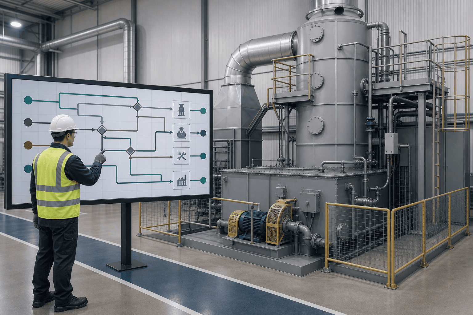
The lifecycle matrix prevents a common procurement error: asking one page—or one supplier conversation—to answer every question. Read across the row that fits your situation, confirm the decision it forces, and follow the detailed guide. The values in the evidence column are qualified examples from published XICHENG guides, not universal acceptance limits.
| Lifecycle stage | The decision this stage forces | Evidence that tells you that you are here | Detailed guide |
|---|---|---|---|
| Selection and design | Is wet absorption the right control route, and what input package is needed before equipment design? | Example duty: 10,000 cfm gas flow and 300 gpm circulation; EPA notes most absorbers can exceed 90% removal depending on the pollutant and absorbent | How industrial scrubbers work and the gas-stream selection and staging guide |
| Installation | Is the site, piping, instrumentation, leak test, and commissioning record ready for acceptance? | Illustrative project: 20,000 Pa leak test for 30 min and a 10-week installation sequence; project/vendor criteria govern | Wet scrubber installation checklist |
| Operation and troubleshooting | Is the performance change an operating fault, an instrument problem, or evidence of asset degradation? | Sustained pressure-drop drift near 20% above baseline triggers inspection; 40–50% drift can indicate fouling or blocked internals | Common wet scrubber problems and troubleshooting |
| Rebuild or retrofit | Can the shell carry another service interval, and will renewing internals restore the required result? | Qualified guideposts: shell retention at or above about 85%, bed loss of 10–30%, and pressure-drop evidence read together | Inspection-based rebuild and retrofit assessment |
| Facility and utilities | Can the room, drainage, utilities, ventilation, and maintenance path support the chosen scope? | Planning references: 15–20 gpm blowdown on a 25,000 cfm example; 0.05–0.10 in. w.c. room pressure differential and 6–12 air changes per hour for local confirmation | Scrubber room layout and utility requirements |
| Delivery resources | Is the process, equipment, site, and acceptance data complete enough for a supplier to quote one defined scope? | RFQ examples should state gas flow in cfm, liquid flow in gpm, inlet temperature in °F or °C, outlet target, utilities, schedule, and acceptance basis | Request an engineering quote |
How to read the matrix in a running project
Start with the unresolved decision. A running tower with verified pressure-drop drift begins in operation, then moves to rebuild; new access or fan requirements move it to facility planning before delivery.
A new project starts with gas data, then generates facility and installation inputs. Complete the first unresolved row and carry its record forward.
Decision point: You can now select one matrix row, state the evidence needed to close it, and open the detailed guide without asking another stage to answer the wrong question.
Selection and Design: Start with the Gas Stream, Not the Vessel
Selection begins with the gas, pollutant, and outlet requirement. A tower model cannot compensate for missing inlet flow, concentration, temperature, moisture, particulate load, or chemical compatibility data. The purpose of this stage is to confirm the control approach and assemble the inputs a qualified supplier will use—not to choose dimensions from a generic table.
When a wet scrubber is the right control
Wet absorption fits when the pollutant transfers into the selected liquid and the facility can manage the blowdown. The EPA monitoring framework names pressure differential, liquid flow, and outlet concentration or removal efficiency as primary indicators. EPA reports that most absorbers can exceed 90% removal when the pollutant and absorbent are properly matched; that is not a guarantee for every duty.
Dry particulate, poorly soluble organic vapor, or an unacceptable wastewater burden may require another route. If the fit is unresolved, use the industrial scrubber principles guide before requesting equipment.
What you must know about the gas before selecting
Record gas flow at operating temperature, pollutant species and concentration, moisture, particulate content, inlet temperature, outlet target, operating hours, upset conditions, and the wastewater route. A measured 10,000 cfm acid-gas stream under actual load is not the same design problem as the same flow carrying dust and low-solubility vapor.
Also state liquid flow and fan duty. One installation example records 300 gpm beside 10,000 cfm only to show the input format. Label each value as measured, design, or open, and record its source and date for supplier and procurement review; the same 10,000 cfm has a different meaning as a measured peak than as a preliminary estimate. The selection and staging resource and supplier calculation set the project value; this map does not supply a design ratio.
Where selection hands off
Selection is complete when the project has a process basis, equipment configuration, performance target, and drawings that state operating weight, connections, utilities, pressure drop, and access needs. Those outputs feed installation and room planning.
Do not release a purchase order with blank site interfaces. Close the gas-stream decision, drain, makeup water, power, and removal-path questions, then hand a dated design basis to the installation team.
Decision point: You can now decide whether wet absorption remains in the shortlist and assemble the process data package required before detailed equipment design begins.
Installation: Turn the Design into a Field-Ready System
Installation converts vendor drawings into an accepted operating baseline. The project is not delivered when the tower is standing; it is delivered when site readiness, receiving, piping, instrumentation, leak testing, commissioning, and handover records have passed their stated criteria.
Site readiness and acceptance gates
Start with the full-operating weight, not the empty shipping weight. One qualified installation example compares a 12,000 lb empty tower with a 25,000 lb filled operating condition and a 30,000 lb rated lift. The values are illustrative, but the rule is firm: the vendor foundation drawing and local code govern the pad, anchors, lifting route, and service clearances.
Then verify every connection against the P&ID. Your project values come from the vendor and design file; the installation checklist gives the sequence and acceptance records that keep those values attached to the work.
| Installation checkpoint | Illustrative value | Governing source |
|---|---|---|
| Empty / operating tower weight | 12,000 lb / 25,000 lb | Vendor loading drawing |
| Leak test | 20,000 Pa for 30 min | Project design and vendor procedure |
| Circulation and power | 300 gpm; 480 VAC, 20 kW | P&ID and electrical schedule |
Commissioning is the handoff to operations
Commissioning establishes the readings that later teams need. Record pressure drop at design gas flow, liquid flow, pH or the selected chemistry indicator, outlet concentration, pump condition, and alarm/interlock checks. A ten-week installation example moves through site readiness, receiving, piping, leak testing, pre-start, and commissioning; it is a planning illustration, not a delivery promise.
The handover package should contain the incoming inspection, P&ID walk-down, calibration certificates, leak-test record, pre-start checklist, commissioning readings, vendor drawings, and operating manual. Without those records, a later 20% pressure-drop increase has no reliable baseline. Installation ends only when the operating team can compare today’s readings with an accepted start.
Decision point: You can now decide whether the installed system is ready for handover and name every acceptance record that must exist before routine operation begins.
Operation and Troubleshooting: Read the Whole Gas-Liquid System
Underperformance is a system symptom until measurements isolate the cause. Pressure drop, liquid distribution, pump condition, chemistry, packing, mist elimination, duct leakage, and instruments interact; replacing one visible component before reading the system can preserve the fault and spend the outage budget twice.
The variables that localize a fault
Compare pressure drop at the same gas flow against the commissioning baseline. Use the ranges as inspection prompts rather than automatic replacement limits.
| Signal at the same design flow | Qualified guidepost | First action |
|---|---|---|
| Total pressure-drop drift | About +20% sustained | Verify instruments, flow, and internal condition |
| Severe pressure-drop drift | About +40–50% | Inspect packing, distributor, support, and mist eliminator |
| Clean mist-eliminator pressure drop | About 0.5–1 in. w.c. | Compare with its own baseline before cleaning/replacement |
Read those values with liquid flow, pump current, pH trend, gas flow, and outlet concentration. A pH probe drifting by 0.5–1.0 pH unit, a cavitating pump, or a blocked suction strainer can mimic lost absorption area. Use the fault-diagnosis guide to verify instruments and rotating equipment before the project enters a capital decision.
When troubleshooting becomes a rebuild question
The branch changes when calibrated instruments and pumps are sound but the degradation remains. Persistent pressure-drop drift, lost bed height, damaged supports, nonuniform spray coverage, wall loss, or mist-eliminator deterioration move the work from operating diagnosis to an outage inspection. The handoff is a measured problem statement, not “the scrubber is old.”
The EPA Wet Scrubber Inspection and Evaluation Manual frames the same symptom-to-record-to-evaluation discipline. A maintenance program should keep dated readings, instrument IDs, calibration status, operating load, and corrective actions. Escalate only when the records show a sustained asset condition.
Decision point: You can now separate an operating fault from an asset-degradation signal and prepare the evidence required for a rebuild assessment.
Rebuild or Retrofit: Decide on Evidence, Not Budget Alone
A rebuild keeps a structurally credible shell and renews the parts that restore performance. Replacement becomes the defensible route when the shell, process duty, emission limit, or available fan/facility capacity cannot support another interval. Price comes after that branch, not before it.
What a rebuild assessment covers
Inspect the shell and welds, packing height and support, distributor and nozzles, mist eliminator, pump, fan, instruments, duct connections, and support steel. Record wall thickness in inches or millimeters, pressure drop in in. w.c., liquid flow in gpm, pump current in amperes, and bed height against the design reference. A qualified engineer confirms the thresholds for the material and service.
The published rebuild and retrofit assessment uses guideposts rather than guarantees: roughly 85% or more wall retention supports the rebuild branch, below about 70% tends toward replacement, and a 10–30% bed-height loss can support packing renewal when the support and shell remain sound. These numbers make the inspection comparable; they do not replace material-specific engineering judgment.
Evidence changes the scope
Consider a tower whose pressure drop moves from 4.5 to 7.8 in. w.c., whose 48 in. bed settles to 41 in., and whose local wall reading falls from 0.375 to 0.28 in. The pattern is not solved by ordering packing alone. The team must read whether the wall loss is localized, whether the support is intact, and whether the fan can carry the restored system curve.
A repair may still be the right answer for a blocked nozzle, failed gasket, worn seal, or local shell patch. A rebuild renews internals inside a sound shell. Replacement is favored by through-wall damage, widespread cracking or embrittlement, a changed pollutant, a tighter outlet limit, or insufficient geometry. The inspection record, not the equipment tag year, defines the scope.
When replacement beats rebuild
Replacement is not a failure of maintenance when the process basis has changed. A new pollutant, higher flow, lower permitted outlet concentration, or incompatible shell material can make the original tower wrong even after every internal component is renewed. The project then returns to selection, with the current gas data as its new design basis.
Facility capacity can make the same decision. A rebuild that needs a larger fan, a 460 VAC motor, or a removal path the existing room cannot provide may cost more downtime than a planned replacement in another location. Move those constraints to the facility row before the budget holder compares quotations.
Decision point: You can now classify the project as repair, rebuild, or replacement from measured shell, internals, performance, process, and facility evidence.
Facility and Utilities Planning: Fit the System into the Building
The room is part of the control system. Access, lifting, drainage, containment, ventilation, makeup water, power, instrument air, and fan duty determine whether the selected or rebuilt package can be installed, operated, and maintained without a later construction change.
Space, access, and lifting decisions
Use the vendor general-arrangement and loading drawings to set the envelope. A vertical industrial tower may require roughly 15–40 ft (4.6–12.2 m) of clear height depending on gas flow and packing depth; a horizontal unit trades height for floor area. Reserve operating access, packing-removal space, lifting clearance, electrical service space, and a door path sized to the largest replaceable component.
Do not copy a generic clearance. The scrubber room planning guide shows how to record the zones and make the vendor or qualified designer supply the dimensions.
| Facility interface | Qualified planning reference | Who confirms it |
|---|---|---|
| Vertical tower clear height | About 15–40 ft (4.6–12.2 m) | Vendor general-arrangement drawing |
| Mid-size pump component | About 150–400 lb | Vendor replacement-parts sheet |
| Packing bed on a 25,000 cfm example | About 1,500–3,000 lb | Media schedule and lift plan |
Utilities, drainage, and containment inputs
A qualified 25,000 cfm example uses 15–20 gpm (57–76 L/min) of blowdown as a planning figure, while the vendor water balance sets the project value. Room ventilation may start with a 0.05–0.10 in. w.c. negative-pressure target and a 6–12 air-change-per-hour screening range. In a 12,000 cu ft room, that range corresponds to about 1,200–2,400 cfm of exhaust, subject to the chemical list, local code, and the authority having jurisdiction.
The room also needs permitted blowdown routing, a contained chemical area, makeup water, fan and pump power, controls, and any instrument-air connection. The scrubber-water planning resource owns the liquid-management detail. Your output here is a Facilities Input Data Sheet that states each confirmed value and names every open item for the designer, contractor, or supplier.
Decision point: You can now decide whether the existing room supports the selected scope and issue a complete facility-interface list before equipment or construction is released.
Delivery Resources: What to Prepare Before Requesting a Quote
A comparable quote starts from a fixed project input set. “Need a scrubber” is not a scope; gas, pollutant, performance, site, utility, schedule, and acceptance data are the scope. The supplier should see which values are measured, which are design targets, and which remain open.
The RFQ input list
Provide gas flow in cfm at the operating temperature, inlet temperature in °F or °C, moisture, pollutant species and concentrations in ppm or mg/m³, particulate load where relevant, required outlet limit, operating hours, and upset conditions. Add available footprint and height, duct connections, power supply, water quality and flow, blowdown destination, instrument air, material constraints, and the permit/AHJ status.
For an existing asset, attach commissioning and inspection records: baseline and current pressure drop in in. w.c., liquid flow in gpm, pH or chemistry indicator, wall readings in inches or millimeters, bed height, pump current, fan duty, photographs, and the repair/rebuild/replace branch. State the required outage window and the acceptance test the delivered scope must pass.
| RFQ field | Illustrative entry | Boundary |
|---|---|---|
| Process flow and temperature | 25,000 cfm at 100 °F (38 °C) | Replace with measured design basis |
| Blowdown planning value | 15–20 gpm (57–76 L/min) | Vendor water balance and permit govern |
| Electrical service | 460 VAC, 3-phase, 60 Hz | Site service and motor schedule govern |
| Fan static-pressure allowance | About 2–8 in. w.c. | Vendor curve and duct calculation govern |
Packed-bed scrubbers as a workhorse option
Packed towers provide gas-liquid contact area for many soluble-gas and acid-fume duties, but pollutant chemistry, particulate load, wastewater, pressure drop, and material compatibility still decide the fit. Where that route is confirmed, the packed-bed scrubber product family is the single product handoff.
The RFQ must let a supplier reject an unsuitable route. A defensible quotation states its assumptions, exclusions, design inputs, and acceptance basis.
What happens after you submit the inputs
The supplier should return an equipment basis, drawing, utility schedule, fan duty, materials, instrumentation, scope boundaries, schedule, and exclusions. Compare proposals against the same inputs; a lower price with a different inlet load or missing wastewater scope is not the same project.
Resolve deviations in writing. The selected package then feeds facility and installation work without forcing the next team to recreate the process basis.
Decision point: You can now send one supplier-ready input package and compare quotations against the same process, facility, and acceptance basis.
Worked Example: Walking a Failing Scrubber Through the Lifecycle Map
The following example shows how a project moves between rows without repeating the detailed guides linked above. The values are illustrative and come from the published rebuild framework; they are not a XICHENG project record or performance promise.

The situation and the first check
An existing packed tower handles 18,000 cfm of exhaust with a design inlet of 500 ppm HCl. Its commissioning baseline is 4.5 in. w.c. total pressure drop, pH 9.5, a 48 in. packed bed, and 0.375 in. shell wall readings at the marked grid. Current pressure drop is 7.8 in. w.c., about 73% above baseline, while pH holds near 8.2 and reagent use rises.
The project starts in operation, not rebuild. The team calibrates the pH and differential-pressure instruments, verifies gas and liquid flow, checks the pump and strainer, and examines the spray pattern. Those checks rule out a probe error and a simple hydraulic fault. Persistent drift moves the project to the rebuild assessment with measured evidence attached.
The rebuild-versus-replace decision
The outage inspection finds the bed at 41 in., about 15% below its 48 in. design height; one distributor arm is blocked; three nozzles are worn; roughly half the mist-eliminator open area is gone; and one local shell panel measures 0.28 in., while most of the shell remains at or above 0.35 in. Pump current runs 12% above nameplate at the same flow.
Because the broad shell condition remains credible and the damage is localized, the result is a repair-plus-rebuild branch: repair the local panel, renew packing, restore the distributor/nozzles, replace the mist eliminator, and inspect the pump. If the low wall reading were widespread or the emission limit had tightened beyond the tower geometry, the same matrix would move the result to replacement.
Facility constraints and the quote path
Before requesting a price, the team checks whether packing and the mist eliminator can leave through the existing access path, whether lifting points support the heaviest component, whether the fan has reserve for the restored system curve, and whether the room can isolate the planned outage. Those answers define the facility row and prevent a rebuild scope that cannot be executed inside the building.
The RFQ then carries the 18,000 cfm duty, 500 ppm inlet basis, 4.5 and 7.8 in. w.c. readings, 48 and 41 in. bed heights, wall-thickness map, photographs, component list, acceptance targets, outage window, and facility constraints. The supplier is pricing a measured scope rather than guessing from “rebuild the scrubber.”
Decision point: You can now apply the lifecycle route to a real symptom, change the branch when the evidence changes, and produce the records a supplier needs to quote the result.
Frequently Asked Questions
Can a wet scrubber rebuild be completed in place?
Yes, when the shell passes inspection and the room provides safe access, lifting, containment, and removal routes for the internals. In-place work is not credible when packing, demister elements, pumps, or damaged shell sections cannot be reached or removed without unplanned demolition.
Confirm the work path with the rebuild assessment and room layout before asking for a fixed schedule. A 1,500–3,000 lb packing-bed example or a 150–400 lb pump changes the lifting plan; the vendor supplies the actual weights and lift-point limits.
How long does replacement take?
No universal lead time is supportable here. Equipment configuration, materials, supplier capacity, drawings, permits, foundation work, utilities, and site access all change the schedule. A published ten-week installation is an illustrative sequence after design inputs exist, not a replacement lead-time promise.
Ask suppliers to split engineering, fabrication, delivery, site work, commissioning, and acceptance in weeks. Compare the schedule assumptions beside the commercial scope so a missing foundation or permit is not hidden inside an optimistic delivery date.
Does every system need a dedicated scrubber room?
No. Outdoor installations and open plant areas may not require an enclosed room, while cold climate, corrosive chemicals, restricted access, noise, or indoor process routing can make an enclosure useful or necessary. The decision belongs to the facility layout, chemical list, climate, and local code.
Where a room is used, screen negative pressure around 0.05–0.10 in. w.c., ventilation around 6–12 air changes per hour, and weather protection against the local design temperature—then have the HVAC designer and AHJ confirm the values.
Your Next Step: Prepare the Project Inputs and Talk to an Engineer
The wet scrubber project lifecycle becomes actionable when each stage produces a record the next stage can use. Identify your current row, close its decision with measured evidence, and carry the output forward instead of restarting the project at every supplier conversation.
Before requesting a quote, assemble:
- gas flow, temperature, moisture, pollutant species, concentrations, and outlet target;
- current and baseline pressure drop, liquid flow, chemistry indicator, and outlet readings;
- equipment drawings, shell/internals inspection data, photographs, and the selected repair/rebuild/replace branch;
- footprint, height, access, lifting, drainage, containment, utilities, and permit constraints;
- schedule, outage window, scope boundaries, and measurable acceptance criteria.
If the data show that a wet packed tower remains the right route, send the project inputs to XICHENG for an engineering review. The useful outcome is not a fast generic price; it is a proposal that names the design basis, assumptions, exclusions, facility interfaces, and acceptance test for the stage your project is actually in.
Decision point: You can now leave with one stage, one evidence package, and one next action for the wet scrubber project lifecycle.


