
Pollutant scrubber design is the discipline of matching a pollutant’s chemistry, safety boundary, and material limits to the removal route that fits — and it goes wrong at the same point more often than anywhere else: the equipment is chosen before the pollutant’s chemistry is named. Hydrogen sulfide, sulfur dioxide, hydrogen fluoride, hydrogen chloride, chlorine, and ammonia each impose a different solubility profile, a different pH window, a different material limit, and a different safety boundary on the system that removes them. This page routes you by pollutant. You read the decision matrix to find your design inputs, work through three chemistry questions that separate the routes, then follow your pollutant’s row to the guide that carries the full method. A worked three-stream example shows the routing in practice, and the closing checklist turns your concentration, flow, and temperature data into a request-for-quote a vendor can size from.
Key Takeaways
- The scrubber route follows the pollutant’s chemistry, not the equipment catalog. Solubility and reactivity in water decide whether wet absorption can work at all.
- Match the pH window to the acid or base. H2S and SO2 need alkaline liquor; HF sits in its own window; ammonia requires acid, not caustic.
- Materials can veto a route before the chemistry finishes. HF rules out glass and bare carbon steel; wet HCl rules out 304/316 stainless wetted parts.
- Safety boundaries shape the design. H2S is flammable from 4.3 to 45 vol%; chlorine emergency duty is sized from release inventory, not steady flow.
- Send the vendor seven inputs. Pollutant identity, concentration, flow, temperature, pH, particulate, and the existing system — that list returns comparable quotes.
The Pollutant-to-Design-Input Matrix
The matrix is the spine of this page: for each of the six pollutants it names the typical sources, the key design inputs, the one-sentence route judgment, and the guide that carries the full method. Find your pollutant, read the judgment column, then open the owner guide for the complete method — each row links a published guide with verified status, and the matrix is the navigation layer rather than a summary of any of them.
| Pollutant | Typical sources | Key design inputs | Route judgment at a glance | Owner guide |
|---|---|---|---|---|
| H2S (hydrogen sulfide) | Wastewater and leachate tank vents, digester or process gas | Flammable envelope 4.3% to 45% by volume; low water solubility; alkaline liquor with pH control; damp, chloride service | Caustic wet scrubbing fits moderate-to-high humid loads; verify vent flow and peak concentration before sizing | H2S scrubber for wastewater and leachate tank vents |
| SO2 (sulfur dioxide) | Incinerator or sludge-burning mixed flue gas | Quench before absorption; SO2 + HCl combined load; chloride-environment materials; limit line (26 ppmv new SSI) | Wet caustic train with quench absorbs SO2 and HCl together; boiler flue gas is a separate train | SO2 scrubber for incinerator exhaust |
| HF (hydrogen fluoride) | Semiconductor, glass, metal finishing | Glass and bare steel fail in HF service; fluoropolymer wetted zone; wet vs dry screening (1 g/m³ at 80 °C); fluoride wastewater | Materials decide before chemistry — confirm the material window, then choose wet or dry | HF scrubber design |
| HCl (hydrogen chloride) | Pickling, chemical, reactor vents | Fast absorption in water and caustic; reagent dosing; blowdown and chloride wastewater; mixed-acid peaks | Compact packed bed with caustic and pH control; the wastewater route is part of the design | Acid scrubber system design |
| Cl2 (chlorine) | Chlor-alkali, water treatment, pulp, chemical | Caustic stoichiometry; hypochlorite byproduct; process vs emergency duty; release inventory | Emergency scrubbing is sized from the release inventory; process duty from the measured envelope — two designs | Chlorine gas scrubber for emergency treatment |
| NH3 (ammonia) | Refrigeration, fertilizer, semiconductor, chemical | Ammonia is a base; acidic liquor (H2SO4, pH 2–5); ammonium-salt crystallization and blowdown | Acid scrubbing, not caustic; salt handling in the blowdown is a design input | NH3 scrubber design |
| Mixed acid (HCl/HF/H2SO4 …) | Multi-acid exhaust, semiconductor etch, electroplating | Design for the most demanding species; no compromise pH window | Two or more acids arriving together need staged or segregated handling, not one average setpoint | See the HCl mixed-acid section on this page |
Hard numbers in the matrix carry the source boundary of the row’s owner guide. The flammable envelope, pH bands, and limit values above are taken from the published guides named in each row, and those pages carry the underlying citations; no value here was imported from a competitor page.
To read the matrix: find your pollutant row, treat the key design inputs as the numbers you must collect, treat the route judgment as the working hypothesis, and open the owner guide when you need the full method. If your stream carries two or more acids, the mixed-acid row applies before any single row.
Decision point. The six rows are the full routing spine. By the end of this page you can name your pollutant’s row, collect the inputs that row lists, and decide whether to continue with the three questions or jump straight to your pollutant’s section.
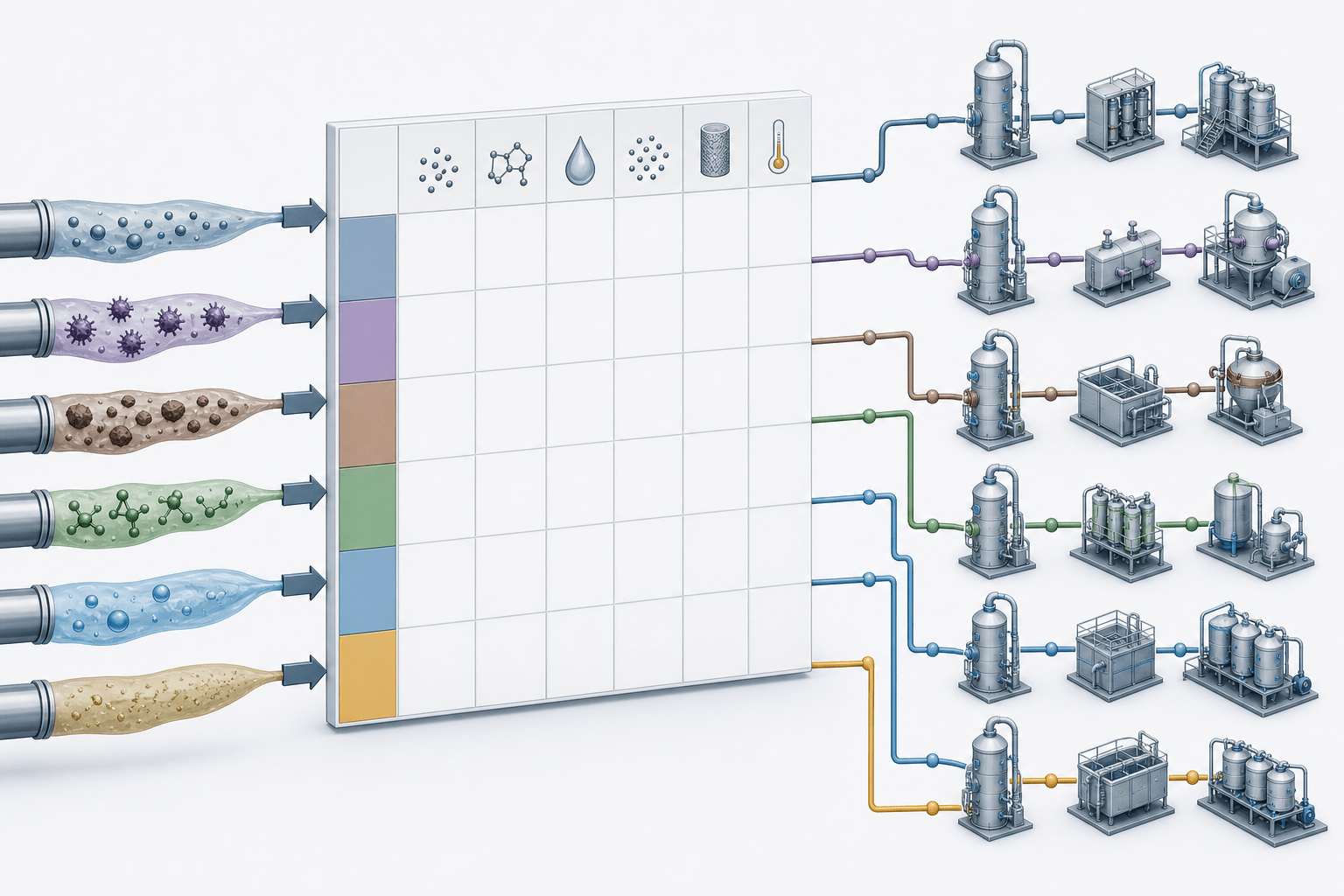
Three Questions Before Pollutant Scrubber Design
Before any tower, reagent, or vendor conversation, the pollutant scrubber design decision reduces to three questions: is the pollutant soluble or reactive in water, which pH window does its acid-base chemistry need, and do temperature, particulate, or co-pollutants change the route. Answer those three and the wet route either fits, needs a conditioning stage, or is the wrong first choice. The mechanics of how wet scrubbers absorb gases are covered in our overview of industrial wet scrubbers; here the focus is the judgment itself.
Is the Pollutant Soluble or Reactive in Water?
Wet absorption works only when the gas will leave the air and stay in the liquid. HCl dissolves quickly and neutralizes on contact with caustic; SO2 dissolves to sulfurous acid; ammonia dissolves readily in water; HF is fully miscible with water, with a boiling point of 19.4 °C and a vapor pressure of 783 mmHg (NIOSH Pocket Guide entry, as cited in our HF scrubber design guide). H2S has low water solubility, which is why its design leans on more contact surface and alkaline liquor rather than plain water absorption. Chlorine reacts with caustic rather than dissolving into plain water at a rate useful for an emergency duty.
The judgment is: a gas that is neither soluble nor reactive in water will not stay captured by a wet scrubber, no matter how tall the tower. That class — insoluble VOCs, hydrides, fluorinated process gases — routes away from wet absorption, and the section on when a wet scrubber is not the answer carries the triage.
Acidic or Alkaline — Which pH Window Do You Need?
The pH window follows the pollutant’s acid-base chemistry, not the vendor’s catalog. For H2S, the dissolved sulfur splits roughly evenly between H2S and bisulfide at pH 7, and at pH 8–9 only about 10% remains as dissolved H2S ready to re-volatilize — which is why caustic H2S scrubbers are controlled on pH (our H2S tank-vent guide). For SO2, absorption efficiency rises with liquor pH, and the caustic circuit also neutralizes the HCl that arrives with incinerator exhaust. HF wet scrubbing typically circulates 5–10% NaOH at pH 7–9 (our HF scrubber design guide); the acid-system design guide reports that matching HCl-grade removal with HF requires pushing the liquor toward pH 10–12 with 1.5–2.0 m of packing — the two published windows are bound to their sources, and the setpoint is confirmed against the actual inlet concentration. Ammonia reverses the rule: it is a base, so the recirculating liquor is held acidic at pH 2–5, not alkaline.
The judgment: name the pollutant’s acid or base character, write the target pH window from the matching published guide, and let that window set the reagent. A mixed-acid stream cannot use one compromise window — it needs staging or segregation, handled in the mixed-acid section below.
Hot, Dusty or Mixed Streams Change the Route
Temperature, particulate, and co-pollutants can veto a route even when the chemistry is right. Incinerator exhaust can leave the furnace above 800 °F and is quenched to saturation before the absorber, because FRP and polypropylene internals are rated below roughly 350 °F (our incinerator SO2 guide). Particulate favors a venturi stage or pre-separator ahead of the packed bed; fine solids that load the packing raise pressure drop and maintenance. And a stream with several pollutants must be designed for the most demanding species, not the average concentration — the acid-system design guide makes this explicit for mixed acid loads.
The judgment: hot gas means quench or high-temperature construction, dusty gas means an upstream particulate stage, and a multi-pollutant stream means the limiting species sets the design. When several of these conditions arrive together, the multi-stage scrubber selection guide is the routing tool to use.
Decision point. You can now state, in one sentence, whether wet absorption fits your pollutant and what conditioning it needs: solubility and pH window set the chemistry, temperature and particulate set the staging.
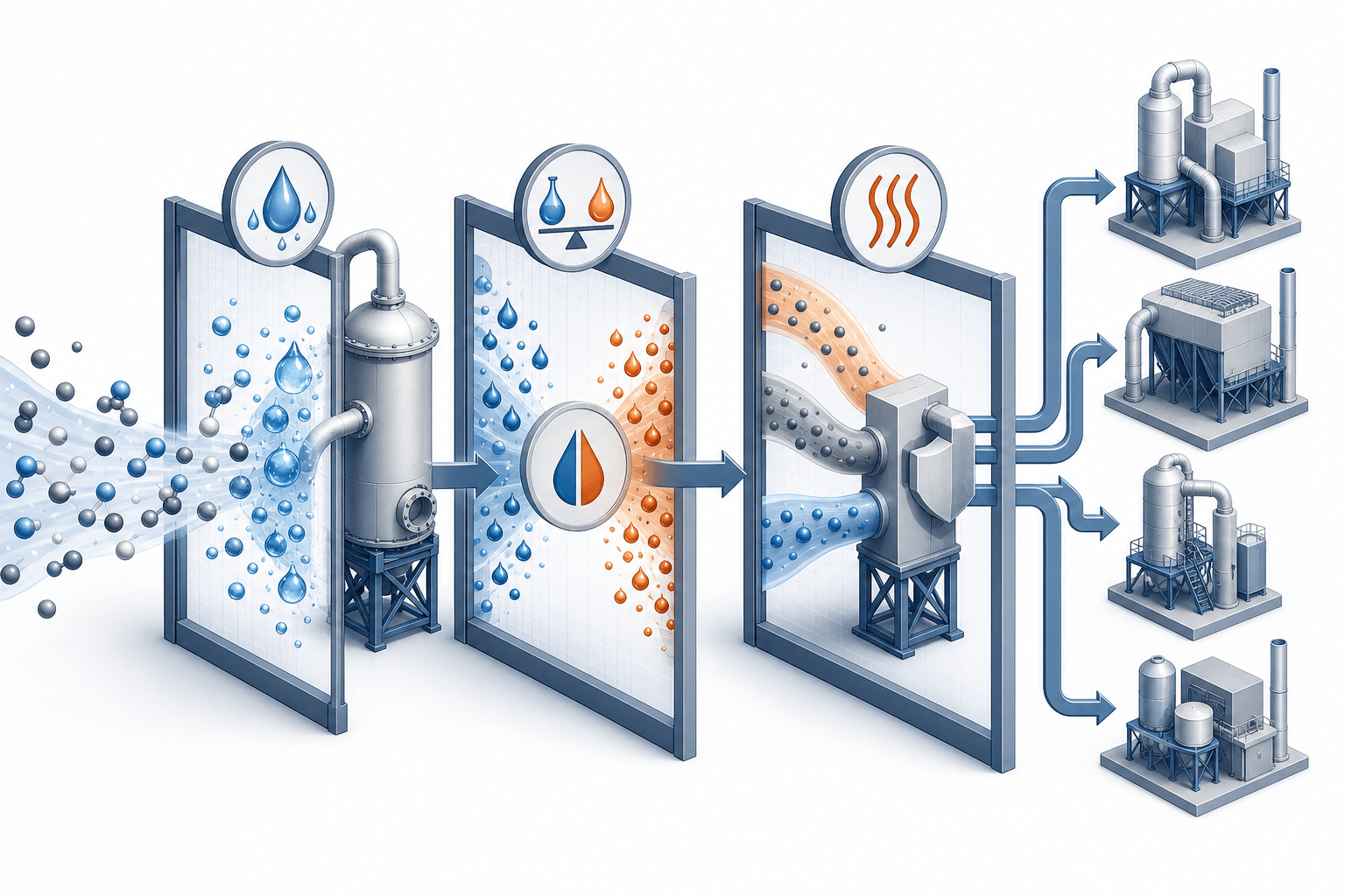
H2S: The Flammable, Low-Solubility Duty
Hydrogen sulfide from wastewater tank vents and leachate exhaust is the duty where the explosive envelope and the vent flow come before any chemistry: the gas is heavier than air, flammable across a wide band, and low in water solubility. The full assessment order — quantifying the vent, route comparison, design inputs, and monitoring — is in our H2S scrubber guide for wastewater and leachate tank vents; this section gives the judgment the matrix row compresses.
The Explosive Envelope That Constrains the Vent System
H2S has a lower explosive limit of 4.3% and an upper explosive limit of 45% by volume, so a vent line, a fan, and a treatment vessel are potential ignition points, not open drains (our H2S tank-vent guide, which cites OSHA and NIOSH for the exposure limits). Its vapor density of 1.09 relative to air makes a released cloud sink and pool at grade instead of dispersing upward.
That envelope changes the design in concrete ways: grounding and bonding on the vent train, negative-pressure arrangement so the fan cannot push a flammable pocket through, and ignition-source control around every accessible point. The exposure side is equally unforgiving — the odor threshold sits at 0.01–1.5 ppm, the OSHA general-industry ceiling is 20 ppm (as documented on OSHA’s hydrogen sulfide page), and olfactory fatigue between 100 and 150 ppm makes “I can’t smell it anymore” a danger sign, not relief — so direct discharge is not a defensible choice.
Decision point. If the headspace can exceed roughly 1 ppm where people work, quantify the vent — flow and peak concentration — before choosing any treatment route.
Chemistry and pH for H2S Service
A caustic wet scrubber absorbs H2S into an alkaline liquid and holds pH as the operating lever. At pH 7 the dissolved sulfur splits about evenly between H2S and bisulfide; at pH 8–9 roughly 10% remains as dissolved H2S, so the pH loop — not a fixed reagent flow — is the control that keeps the gas from re-volatilizing (our H2S tank-vent guide). The absorbed sulfide leaves as sulfide, thiosulfate, and sulfate in the spent liquor, which makes disposal a design input rather than an afterthought.
For low, dry loads, impregnated activated carbon carries roughly 25–50% H2S by weight, but a wet, warm vent burns through media quickly, which is why humid tank vents favor the wet route. The wider chemistry — corrosion mechanisms, oxidation products, and general absorption — belongs to our H2S scrubber design guide.
Decision point. Confirm the vent flow and the peak concentration, then choose the route: caustic wet scrubbing for moderate-to-high humid loads, carbon for low dry loads, and the H2S design guide for the full method.
SO2: Incinerator or Boiler — Two Different Trains
Sulfur dioxide arrives either as hot, mixed incinerator flue gas with HCl alongside, or as the cooler SO2-focused stream of boiler flue gas. The absorption chemistry is the same; the trains are not. Mixing the two design logics is the most common SO2 mistake — the incinerator case needs a quench and chloride materials, the boiler case needs a different reagent and byproduct strategy.
Incinerator Exhaust: Quench Before Absorption, SO2 With HCl
Incinerator exhaust can leave the furnace above 800 °F, so the wet train starts with a quench that cools the gas to saturation before the absorber: FRP and polypropylene internals are rated below roughly 350 °F, and rapid cooling also suppresses dioxin re-formation between about 400 and 700 °F (our incinerator SO2 guide). The quench section is the hottest, most corrosive point, which is why suppliers specify high-alloy grades there while the cooler absorber can run FRP or PP.
The acid load is never SO2 alone. New sewage-sludge incinerators are regulated under 40 CFR 60 Subpart LLLL, which covers nine pollutants — PM, HCl, dioxins/furans, mercury, NOx, SO2, cadmium, lead, and CO — and sets the new-source SO2 limit at 26 ppmvd on a three-run basis (40 CFR 60 Subpart LLLL, as cited in our incinerator SO2 guide). The same caustic circuit that absorbs SO2 neutralizes the HCl, so the two acids share one reagent loop, and the design target comes from the applicable limit line — NSPS for new units, the permit line for existing ones, which can be tighter.
Decision point. Name your furnace type and feed, confirm the applicable limit line, and choose the mixed SO2 + HCl design with a quench — not SO2 alone.
Boiler Flue Gas: A Separate Reagent Strategy
Boiler flue-gas desulfurization is a different scale and a different byproduct story. Lime or limestone circuits suit large gas volumes and produce gypsum that can be dewatered to about 10% residual moisture and handled as a solid; incinerator-scale loads instead default to caustic, where the same loop absorbs SO2 and HCl and the byproduct is a liquid blowdown of sodium sulfite, sulfate, and chloride. Copying a boiler FGD specification onto an incinerator stream fails on materials, on the mixed acid load, and on the missing quench.
Decision point. If your source is a boiler rather than an incinerator, choose the SO2 scrubber system design for flue-gas desulfurization — the two trains are not interchangeable.
HF: Materials Decide Before Chemistry
Hydrogen fluoride breaks the usual material assumptions before any absorbent is chosen. HF is fully miscible with water but it attacks glass and concrete, which rules out glass-lined steel and bare carbon steel in the wetted zone and forces a fluoropolymer-based material set — the first design decision is survival, not reagent. The complete wet-vs-dry method, blowdown math, and monitoring set are in our HF scrubber design guide.
Why HF Breaks the Usual Material Assumptions
HF’s physical properties make a release a fast-moving exposure event: it is fully miscible with water, has a boiling point of 19.4 °C, and carries a vapor pressure of 783 mmHg (NIOSH Pocket Guide entry 0334, as cited in our HF scrubber design guide). It is also a weak acid — pKa about 3.17 at 25 °C — so absorption is mass-transfer-limited rather than ionization-limited, and design work is required for the actual inlet range.
The material rule follows directly. NIOSH records that HF will attack glass and concrete and is incompatible with metals in the wetted context: glass-lined steel fails at any breach point, and bare carbon steel is attacked even at modest concentration. The wetted zone stays fluoropolymer-based — ECTFE, ETFE, PVDF, or HDPE — with the exact grade bound by the resin-maker’s HF compatibility table at the actual inlet temperature and concentration.
Decision point. Lock the material window first: fluoropolymer internals in the wetted zone, no glass, no bare carbon steel — then evaluate chemistry.
Wet or Dry: A Route Test Before Reagent Choice
The wet/dry branch is a decision tree, not a debate. As screening — clearly marked as screening in our HF scrubber design guide, not universal limits — the wet packed bed is the default when inlet HF is at or below 1 g/m³ and the gas is below 80 °C, with 5–10% NaOH at pH 7–9 and fluoropolymer internals; the dry calcium-sorbent route fits inlet HF at or above 5 g/m³ above 80 °C when the plant has a calcium-fluoride sink and can handle the captured solid. Between those points, measured chemistry, temperature, flow, wastewater capacity, and solid-handling economics decide. The acid-system design guide reports that matching HCl-grade removal with HF pushes the liquor toward pH 10–12 with 1.5–2.0 m of packing — record both published windows and confirm the setpoint against the actual inlet concentration.
The wastewater follows the wet route: fluoride ends up in the blowdown, treated by calcium precipitation — CaF2 has a solubility product of about 3.9 × 10⁻¹¹ — and the discharge target is the applicable state industrial NPDES limit, not the 4 mg/L federal drinking-water MCL (our HF scrubber design guide makes the distinction explicit).
Decision point. Material window first, then the wet/dry screening at 1 g/m³ and 80 °C, then the blowdown-permitting check before reagent choice.
HCl: Fast Absorption, pH and Blowdown Discipline
Hydrogen chloride is the easy absorption case and the easy one to under-engineer: it dissolves quickly and neutralizes on contact, so capture is rarely the problem — reagent balance, mixed-acid peaks, and chloride-laden wastewater are. The system-level method lives in our acid scrubber design guide; this section carries the routing judgment.
Absorption Chemistry and Reagent Balance
HCl is highly water-soluble and reacts with caustic essentially on contact. The acid-system design guide reports removal above 99% at 1.0–1.5 m of packing with a liquid-to-gas ratio of 2.0–3.5 L/m³, and our semiconductor packed-bed guide holds strong-acid pH control in the 7.5–9.5 band. The reagent balance is molar: 1 mol of HCl consumes 1 mol of NaOH. As an example of the arithmetic, 2,000 cfm at 50 ppmv HCl carries roughly 0.6 lb/h of HCl, so the 100% NaOH demand is on the same order — about 0.6 lb/h — before dosing excess and solution strength are applied (I-INFERENCE: the example assumes 25 °C and 1 atm; verify with your measured concentration and flow).
Decision point. Collect the measured concentration and flow, set the pH loop, and choose the reagent supply from the peak load, not the average.
When HCl Arrives in a Mixed Acid Load
Mixed acid streams are the rule in semiconductor etch (HCl, HF, and nitric-acid fumes together), electroplating (HCl with sulfuric-acid mist), and chemical reactor vents (HCl with SO2). The acid-system design guide is explicit: such a stream is designed for the most demanding species present, not for the average of the acids. Under the Semiconductor Manufacturing NESHAP, HCl and HF are two of the five hazardous air pollutants that together account for more than 90% of semiconductor HAP emissions (our semiconductor packed-bed guide), which is why the classification unit is the acid header, not the individual tool.
When two or more acids arrive together, compare the chemistries before blending them into one tower: windows, materials, and wastewater differ per acid. The compliance comparison across jurisdictions is the routing link here — see our acid fume scrubber systems guide for HCl, HF and sulfuric acid.
Decision point. If your stream is a single acid, choose the compact packed bed with caustic and pH control; if it is a mixed acid load, the limiting species sets the design and the compliance guide is the next stop.
Chlorine: Process Duty and Emergency Response Differ
Chlorine scrubbing splits into two designs that share chemistry but little else: the continuous process scrubber sized from a measured emission envelope, and the emergency scrubber sized from a defined release inventory, stored reagent reserve, and a tested response sequence. Treating an emergency duty with a process-scrubber basis is the failure mode this section exists to prevent. The full method — release-case analysis, chemistry, materials, and interlocks — is in our chlorine gas scrubber guide for emergency treatment.
Routine Chlorine Scrubbing Versus Emergency Release Design
A continuous chlorine scrubber handles the site’s measured or specified envelope: cylinder-valve packing leaks, tank venting during temperature cycling, loading-arm disconnects, and process vents, with recirculated caustic and pH control. An emergency scrubber is sized from the facility’s defined release case — connected inventory, credible release fraction and duration, capture efficiency, and reagent reserve — and it must work on first activation: automatic fan start on detection, backup power, and a response time demonstrated in cause-and-effect testing. The scale difference is instructive: a 907 kg chlorine inventory corresponds to about 310 m³ of gas near ambient temperature and pressure (our chlorine scrubber guide), so the fan and capture arrangement come from the release scenario, not from a steady-state flow.
Decision point. Name the duty and choose the sizing basis: the release inventory and response sequence for an emergency event, the measured envelope for routine fugitive duty.
Caustic Chemistry and the Limits to Trust
The absorption chemistry is caustic: Cl2 + 2NaOH → NaCl + NaOCl + H2O, a fast and strongly exothermic reaction that produces sodium hypochlorite as a byproduct (our chlorine scrubber guide). The byproduct is an oxidizer, so the recirculating liquor needs blowdown, temperature control, and pH management to keep hypochlorite from building up, and materials in chlorine service are checked against the actual oxidant concentration, temperature, and stress. For scale, a 907 kg release needs about 1,023 kg of pure NaOH at stoichiometry — roughly 6,400 L of a 15 wt% solution including a 1.1× excess factor — and a continuous 5,000 ACFM stream at 10 ppmv draws about 6.7 kg/day of pure NaOH at 100% capture (both figures stated as illustrative in our chlorine scrubber guide). Vendor removal claims without a source boundary are not part of this calculation.
Decision point. Confirm the duty and the release inventory if any, then choose the system and control scope for the defined case — process envelope or emergency event.
Ammonia: Acidic Liquor and Salt Management
Ammonia is the reverse of the acid-gas cases: it is a base, so the scrubber uses an acidic absorbent, and the byproduct — an ammonium salt — drives the blowdown design. The full decision framework — acid versus water scrubbing, wet versus dry media, materials, and salt economics — is in our NH3 scrubber design guide; this section gives the routing judgment.
Absorption Chemistry: Water or Dilute Acid?
NH3 is highly soluble in water, so water-only scrubbing removes ammonia physically, but the acid route is the industry standard because it fixes the ammonia as a non-volatile salt: 2NH3 + H2SO4 → (NH4)2SO4, run with dilute sulfuric acid at 10–30% by weight and a recirculating liquor held at pH 2–5 (our NH3 scrubber design guide). Below pH 2, excess acid wastes reagent; above pH 5, the equilibrium shifts back toward volatile NH3 and re-volatilization becomes a secondary emission source. Acid scrubbing runs at a liquid-to-gas ratio of roughly 2–4 L/m³, while water-only scrubbing needs 5–10 L/m³ because there is no chemical reaction to accelerate transfer. The OSHA permissible exposure limit is 50 ppm as an 8-hour TWA, so both compliance and odor drive the target outlet.
Decision point. Ammonia routes to acid, not caustic; confirm the measured loading, set the pH 2–5 window, and decide between acid scrubbing and water-plus-recovery on the project mass balance.
Ammonium Salts, Blowdown and Winterization
The absorbed salt is the second design problem. The scrubbing liquor carries dilute sulfuric acid at pH 2–5 together with dissolved ammonium sulfate at 10–40% by weight — a combination more aggressive than either component alone, with sulfate accelerating pitting in stainless steel and ammonium attacking ester bonds in polyester and vinyl-ester resins (our NH3 scrubber design guide). Blowdown handling, and the downstream crystallizer where the salt is to be recovered, follow the same mass balance that sized the tower.
Salt solubility sets the cold limit: the ammonium-sulfate concentration is held below its solubility curve at the minimum operating temperature, which is the check that decides insulation or heat tracing. For scale, a 10,000 ACFM stream at 500 ppmv NH3, 25 °C and 1 atm, at 100% capture around the clock, produces about 550 kg/day of ammonium sulfate before uptime and recovery losses (stated as theoretical stoichiometry in our NH3 scrubber design guide).
Decision point. Size the blowdown for the salt load, check the solubility curve against the winter minimum, and pick the salt disposition — crystallize, handle as liquor, or recover as diluted ammonia — before the equipment is ordered.
Worked Example: Pollutant Scrubber Design on a Three-Stream Plant
This example is a routing exercise only — every input is assumed, the numbers are chosen to show the method, and no plant or equipment is implied (I-INFERENCE throughout). A chemical facility wants to route three exhaust streams through its treatment assessment.
The Stream List and Inlet Conditions
| Stream | Source | Assumed data (I-INFERENCE) |
|---|---|---|
| A | Wastewater tank vent | 150 cfm; H2S 75 ppmv average, 300 ppmv peak; 95 °F; near-saturated |
| B | Pickling bath exhaust | 2,000 cfm; HCl 50 ppmv; 80 °F; mist present |
| C | Ammonia refrigeration vent | 500 cfm; NH3 200 ppmv; 70 °F; dry |
Route Decisions and What to Send the Vendor
Stream A follows the H2S row: flammable envelope 4.3–45 vol%, low solubility, humid gas — so caustic wet scrubbing with pH control fits, sized on the 300 ppmv peak and 150 cfm, with an outlet acceptance target at or below 1 ppmv average (the acceptance discipline from the H2S tank-vent guide). Stream B follows the HCl row: a compact packed bed with caustic and a pH loop; at 2,000 cfm and 50 ppmv the reagent demand is on the order of 0.6 lb/h of 100% NaOH (I-INFERENCE, 25 °C basis). Stream C follows the NH3 row: acid scrubbing with dilute H2SO4 held at pH 2–5; at 500 cfm and 200 ppmv the theoretical ammonium-sulfate production is on the order of 11 kg/day before uptime loss (I-INFERENCE, 25 °C and 1 atm, 100% capture).
The route recommendation for all three streams lands on one equipment family — packed-bed absorption — because each pollutant is captured either by alkaline liquor (Streams A and B) or acidic liquor (Stream C). What the vendor needs is the seven-input list: pollutant identity, concentration with peaks, flow, temperature, pH, particulate or mist present, and the existing system each stream connects to. Those values turn the matrix rows above into comparable quotes.
Decision point. You can now run your own streams through the same chain — matrix row, peak-not-average basis, pH window, material check — and decide with a request-for-quote basis that is defensible.
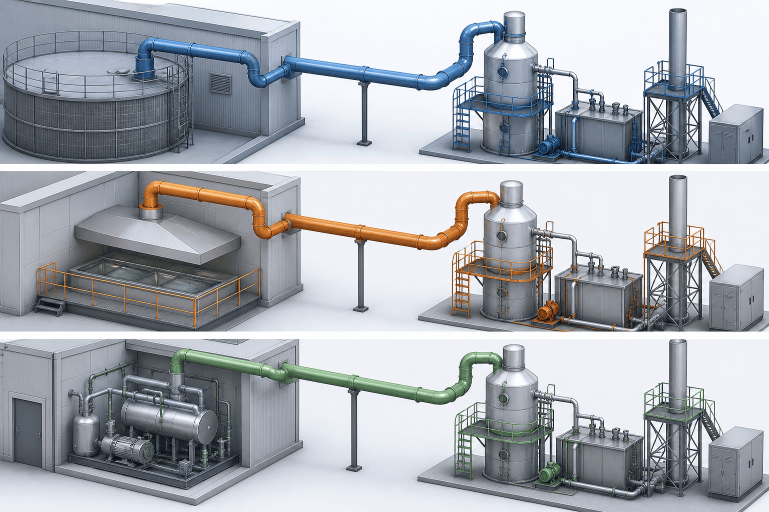
When a Wet Scrubber Is Not the Answer
Wet absorption answers soluble, reactive acid and base loads. When the pollutant class is different, the wet scrubber is the wrong first choice, and the routing is shorter than most people expect.
Streams That Send You Elsewhere
| Stream class | Example pollutants | Why wet absorption fails | Route to |
|---|---|---|---|
| Pure particulate | Dust, fume, solids | A packed bed plugs instead of capturing | Dry collection or a wet electrostatic precipitator |
| Insoluble VOCs and solvents | Many solvent vapors | Water absorption caps many near 90% removal (our semiconductor packed-bed guide) | Carbon adsorption or thermal/catalytic oxidation |
| Hydrides | Silane, phosphine, arsine | Silane is pyrophoric above roughly 1.4% and is diluted below about 0.5% before exhaust; combustion dust plugs packing | Pre-filtration and thermal abatement |
| Fluorinated process gases | CF4, SF6, NF3 | Chemically inert to caustic; pass through a wet bed unreacted | Thermal or plasma abatement |
| Hot gas without a quench path | Above the polymer temperature rating | No conditioning path to saturation before the absorber | Quench first, or a dry route (HF at or above 5 g/m³ above 80 °C, from our HF scrubber design guide) |
The table compresses the triage: the wet scrubber is the right device for soluble, reactive acid and base loads, and the wrong first choice for everything above it. Classification happens before sizing — name the stream class, then the device class follows.
Decision point. If your pollutant is not soluble or reactive, and is not an acid or a base, choose the matching device class from the table — that pollutant scrubber design question routes away from the wet scrubber entirely.
Frequently Asked Questions
Can One Scrubber Chemistry Handle Several Pollutants?
Usually not with one pH setpoint. Each pollutant has its own window — alkaline liquor for H2S and SO2, the HF window for fluoride, acidic liquor for ammonia — so a multi-pollutant stream is either designed for the most demanding species or staged across separate circuits. Verify each pollutant’s solubility and pH window before combining streams; a mixed-acid load in particular cannot use one compromise setpoint. Where targets differ, a quench stage, a primary absorber, and a polishing stage carry different jobs in the same train.
Why Do Recommended pH Windows Differ So Much by Pollutant?
Because pH controls which chemical species stays dissolved in the liquor. For H2S, the split between dissolved H2S and bisulfide swings between pH 7 and pH 8–9; for SO2, removal rises with liquor pH; for HF, the published guidance on this site spans pH 7–9 in the HF design guide and up to pH 10–12 in the acid-system design guide for matching high removal; for ammonia, the liquor must sit acidic at pH 2–5 to hold ammonium in solution. The window follows the equilibrium of each pollutant’s acid-base chemistry — it is not a vendor preference.
Is an Emergency Chlorine Scrubber the Same as a Process Scrubber?
No. They share the caustic absorption chemistry — Cl2 + 2NaOH → NaCl + NaOCl + H2O — but differ in every sizing input: the emergency scrubber is built from the facility’s defined release inventory, duration, capture arrangement, stored reagent reserve, and a tested response sequence with automatic start and backup power; the process scrubber is sized from the measured or specified emission envelope with recirculated chemistry and pH control. Confirm which duty you are designing before any sizing begins — the two are not interchangeable (our chlorine scrubber guide).
Decision point. These answers close the residual questions. If your case still does not fit a matrix row, check the streams-that-send-you-elsewhere list — your pollutant class may route away from wet absorption entirely.
Your Next Step: Send Your Pollutant Data, Get a Route
The deliverable of this page is a data list, and the list is shorter than vendors usually see. Assemble the seven inputs — pollutant identity, concentration including peaks, flow, temperature, pH, particulate or mist, existing system — run them through your matrix row, and the route follows.
If the route lands on packed-bed absorption, the equipment family that carries the alkaline and acidic liquor routes above, the packed-bed wet scrubber product page is the equipment handoff to compare. When you are ready to have the route assessed against your numbers, the request-for-quote form accepts exactly this input list, so the quote is comparable. For the industry-side routing — which exhaust classes belong on which treatment train across a plant — the industrial process exhaust treatment library is the adjacent hub that carries that wider map.
Decision point. Send the seven inputs once, and the routing job is done: the pollutant named, the chemistry window set, the material check run, and a vendor holding comparable data.


