Product Overview
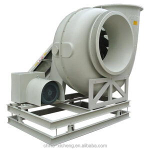
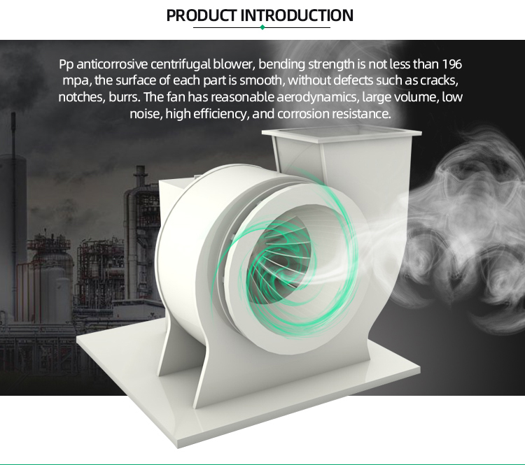
PP/FRP permanent magnet variable frequency drive (VFD) centrifugal fan — combining corrosion-resistant PP/FRP construction with a high-efficiency permanent magnet synchronous motor (PMSM) and integrated VFD for precise speed control and energy savings of 20-40% compared to conventional induction motor fans. Unlike induction motors that operate at fixed speed (1,440 or 2,900 RPM) determined by line frequency, the permanent magnet motor with VFD allows infinitely variable speed adjustment across the full operating range — the fan delivers exactly the airflow and pressure the system requires at any given moment, not the excess that wastes energy through damper throttling. The volute and impeller follow the F4-72 aerodynamic profile with one-piece injection-molded PP impeller balanced to ISO 1940 G6.3.
| Application | Variable-demand exhaust systems — VAV laboratory ventilation, process exhaust with fluctuating production rates, multi-zone systems where airflow demand varies, energy-retrofit replacement of fixed-speed fans |
| Material | PP volute + reinforced PP injection-molded impeller (≤60degC gas); FRP volute + FRP impeller (≤80degC gas) |
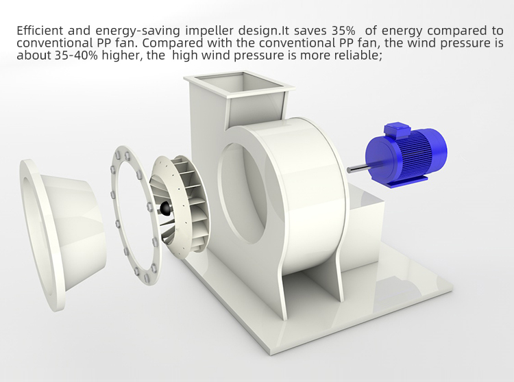
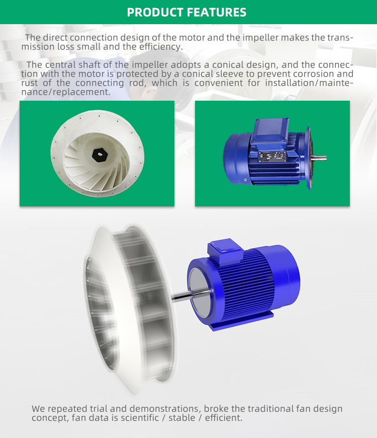
| Motor type | Permanent magnet synchronous motor (PMSM) — direct drive, no belts, no gearbox |
| Drive | Integrated VFD — 0-100% speed range, 0-10V or 4-20mA control signal, Modbus RTU communication |
| Speed range | 0-3,000 RPM infinitely variable; typical operating range 20-100% of maximum |
| Energy savings | 20-40% vs fixed-speed induction motor fan at typical variable-demand duty cycle |
| Model range | XC-5 series — 0.75-11 kW, 2,000-8,000 m³/h standard |
| Lead time | 15-25 days |
Why Permanent Magnet + VFD Changes the Fan Economics
A conventional fan with an induction motor running at fixed speed consumes the same electrical power regardless of whether the system needs the full airflow or only partial airflow. If demand drops, the excess airflow is wasted through damper throttling — converting electrical energy into pressure drop across a damper rather than useful ventilation. The electricity bill doesn’t know the dampers are throttled:
- Affinity laws deliver the savings. Fan power consumption is proportional to the cube of speed — reduce fan speed by 20%, power drops by approximately 50%. A fan running at 80% speed delivers roughly 80% of design airflow at 80% of design pressure, while consuming only 50% of design power. This cubic relationship means even modest speed reductions produce significant energy savings. A VAV laboratory exhaust system where the fan runs at an average 70% of full speed over a year consumes roughly 35% of the energy of the same fan running at fixed full speed with damper control — a 65% reduction. This energy performance supports US DOE laboratory energy efficiency guidelines for demand-controlled ventilation.
- PMSM efficiency vs induction motor efficiency. Induction motors achieve peak efficiency (typically 88-93%) only near full load — at partial load, efficiency drops because the motor still draws magnetizing current regardless of output. Permanent magnet motors maintain high efficiency (93-96%) across a much wider load range because the magnetic field is provided by permanent magnets in the rotor, not by current drawn from the supply. The rotor losses — a significant fraction of motor losses — are essentially eliminated. At 50% load, a PMSM is typically 5-8 percentage points more efficient than an equivalent induction motor.
- Soft start eliminates inrush current. Direct-on-line starting of an induction motor draws 6-8× full-load current for several seconds — stressing the electrical system, causing voltage dips, and potentially triggering protection devices. The VFD provides soft start: the motor ramps from zero to operating speed over a user-adjustable ramp time (typically 10-30 seconds), with starting current limited to 1.0-1.5× full-load current. For facilities with multiple large fans, this eliminates the need to stagger fan starts to avoid overloading the electrical supply.
VFD Control Modes for Industrial Exhaust
The VFD accepts multiple control signals, enabling integration into any building management or process control architecture:
- Manual speed setpoint (0-10V or 4-20mA). The simplest control — a potentiometer or BMS analog output sets fan speed. Used for: manual commissioning, fixed-speed replacement where speed is set once and rarely changed, or simple BMS integration where the BMS calculates required speed from other system parameters.
- Duct static pressure control (PID loop in VFD). A pressure transducer in the main exhaust duct measures static pressure. The VFD’s internal PID controller modulates fan speed to maintain a constant duct static pressure setpoint — as branch dampers open and close, the VFD adjusts fan speed to keep the main header pressure constant. This is the most common control strategy for multi-branch VAV exhaust systems and eliminates the energy waste of a fixed-speed fan with a bypass damper.
- Airflow control (PID with flow measurement). An airflow measurement device (pitot array, thermal anemometer, or differential pressure across a flow station) provides feedback. The VFD modulates speed to maintain a constant airflow — used for processes requiring fixed exhaust rate regardless of filter loading or other system changes.
- Modbus RTU communication. The VFD communicates via RS-485 Modbus RTU protocol — the BMS reads fan speed, power consumption, motor temperature, and fault status directly from the drive without additional sensors. Speed setpoint is written to the drive over the same connection. This two-wire interface eliminates separate analog I/O wiring for each control signal.
Why Xicheng
16 years, 2600+ systems shipped worldwide. A permanent magnet VFD fan is an integrated electromechanical system — the fan, motor, and drive must be engineered as a unit, not assembled from separately-sourced components:
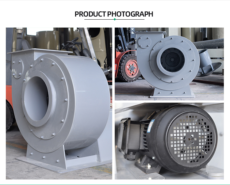
- Factory-integrated motor, drive, and fan — not field-assembled. The permanent magnet motor is directly coupled to the impeller shaft. The VFD is mounted on the fan baseplate, pre-wired to the motor, and programmed with the fan’s specific operating parameters (speed range, acceleration/deceleration ramps, overload limits, resonance skip frequencies). The assembly arrives as a single unit requiring only input power and control signal connections. No field motor-drive matching, no parameter programming, no separate VFD enclosure to mount and wire.
- Resonance skip frequencies programmed at the factory. Every fan-motor-drive combination has natural frequencies at which mechanical resonance occurs — specific speeds where the impeller, shaft, and motor assembly vibrate excessively. Operating continuously at a resonant speed destroys bearings and cracks volute welds. We identify these frequencies during factory run-testing and program the VFD to skip them — the drive passes through the resonant speed during ramp-up and ramp-down but will not operate continuously at that speed. This is standard on our VFD fans and eliminates the most common cause of vibration problems in field-configured VFD installations.
- Energy savings documented, not claimed. We provide a power consumption curve for your specific fan model across the operating speed range — showing input power (kW) vs speed (RPM) and airflow (m³/h). This allows you to calculate expected energy savings based on your actual duty cycle before purchase. VFD energy savings are real but must be calculated for your specific operating profile — a fan running at 95% speed 24/7 saves almost nothing; a fan running at 60% speed for 12 hours per day saves substantially.
- PMSM rotor — no magnets in the airstream. The permanent magnets are in the motor rotor, separated from the fan airstream by the shaft and bearing housing. The motor is mounted externally to the fan casing, with the shaft penetrating through a sealed bearing housing. The magnets never contact corrosive gases — unlike some integrated motor-impeller designs where the magnets are embedded in the impeller hub and directly exposed to the airstream temperature and chemistry.
Send your airflow profile and duty cycle to xicheng023@outlook.com. We’ll calculate energy savings vs fixed-speed alternatives and provide a complete proposal. WhatsApp: +86 18927456906.
Core Advantages
- 20-40% Energy Reduction: Affinity laws — fan power ∝ speed³. Modest speed reductions produce large energy savings. Permanent magnet motor adds 5-8 points efficiency at partial load.
- Infinitely Variable Speed via Integrated VFD: 0-3,000 RPM range, 0-10V/4-20mA/Modbus control. Duct static pressure or airflow PID loops built into the drive.
- Resonance Skip Frequencies Pre-Programmed: Factory-identified and programmed into the VFD — eliminates the most common field-VFD vibration problem.
- Soft Start — No Inrush Current: Starting current limited to 1.0-1.5× FLC vs 6-8× for direct-on-line induction motors. No starter sequencing needed for multi-fan facilities.
- Single-Unit Delivery — Motor, Drive, Fan Pre-Wired: Input power + control signal = operational. No field motor-drive matching, no separate VFD enclosure, no parameter programming.
Key Specifications
| Model No. | XC-5P |
| Material | PP volute + PP impeller (≤60degC); FRP volute + FRP impeller (≤80degC) |
| Motor Type | Permanent magnet synchronous motor (PMSM) — direct drive |
| Drive | Integrated VFD — 0-3,000 RPM, 0-10V/4-20mA/Modbus RTU |
| Motor Power | 0.75 kW to 11 kW standard |
| Motor Efficiency | 93-96% across 30-100% load range |
| Impeller | One-piece injection-molded PP, F4-72 profile, ISO 1940 G6.3 |
| Control Modes | Manual setpoint, duct static pressure PID, airflow PID, Modbus RTU |
| Gas Temperature | PP: ≤60degC | FRP: ≤80degC |
| Service Life | 8-10 Years (fan); VFD per manufacturer rating |
| Brand / Origin | Xicheng / China |
Certifications and Compliance
- CE Certified – Permanent Magnet VFD Fan Assembly
- RoHS Compliant – PP, FRP, and motor materials
- ISO 9001 – Quality Management System
- ISO 14001 – Environmental Management System
- SGS Tested – PP impeller, motor efficiency, VFD EMC compliance
- Design Compliance – Fan designed to meet US DOE laboratory energy efficiency standards, EU Industrial Emissions Directive (2010/75/EU); VFD EMC per IEC 61800-3
How to Order
- You send – Air volume range (min/max), system pressure drop, gas composition and temperature, control mode preference, BMS interface requirements
- We select – Fan model, motor power, VFD configuration, control strategy recommendation
- We calculate – Energy consumption comparison: VFD vs fixed-speed with damper control at your duty cycle
- You approve – Fan curve, energy analysis, control schematic, and pricing
- We build – 15-25 days. Motor mounted, VFD programmed, resonance testing completed, fan run-tested
Contact xicheng023@outlook.com or WhatsApp +86 18927456906 — fan selection with energy savings estimate within 24 hours.
Complete Your System
- PP Centrifugal Fan – Fixed-speed direct-drive fan for constant-demand applications
- PP/FRP Negative Pressure Fan – Belt-driven for negative pressure systems
- Wet Scrubber System – Complete exhaust treatment system
- PP Round Duct – Corrosion-resistant ductwork
FAQ
How much will I actually save with a VFD fan?
It depends entirely on your duty cycle. A fan running at 100% speed 24/7 saves nothing — the VFD itself consumes 2-3% of motor power as conversion losses. A fan running at an average 70% speed over a year saves approximately 65% (power ∝ speed³: 0.70³ = 0.34, or 34% of design power). A fan running at 60% speed saves roughly 78%. The key variable is your actual speed profile — if your system demand varies significantly (multi-zone VAV, batch processes, day/night setback), savings are large. If demand is constant, savings are minimal. Send us your operating profile and we’ll calculate expected savings before you buy.
Permanent magnet or induction motor — which is better for a VFD fan?
Permanent magnet motors (PMSM) are superior for VFD fan applications for three reasons: they maintain high efficiency across the speed range (induction motor efficiency drops at low speed/load), they produce less rotor heat (no induced rotor currents), and they are more compact for the same power rating (higher power density). The trade-off is higher initial cost — permanent magnets (typically neodymium-iron-boron) are expensive. For fans running at high average speed and load, the efficiency advantage may not justify the cost premium. For fans with highly variable duty cycles, the PMSM’s partial-load efficiency advantage typically pays back within 2-3 years.
What happens if the VFD fails — does the fan stop?
Yes. A VFD fan has no bypass to line power — if the VFD fails, the fan stops. For critical exhaust applications where fan stoppage means process shutdown, we recommend either: a bypass contactor (allows direct-on-line operation at full speed if VFD fails — requires a separate enclosure and adds cost), or a redundant fan arrangement (two fans, each with its own VFD, either capable of handling the full load). The bypass approach maintains operation at full speed only. The redundant approach maintains full functionality including variable speed.