Product Overview
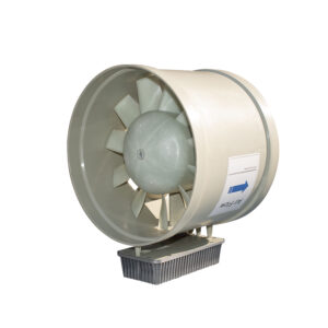
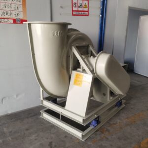
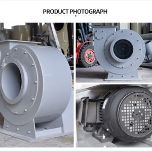
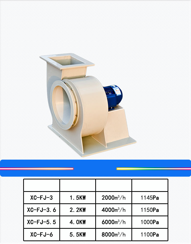
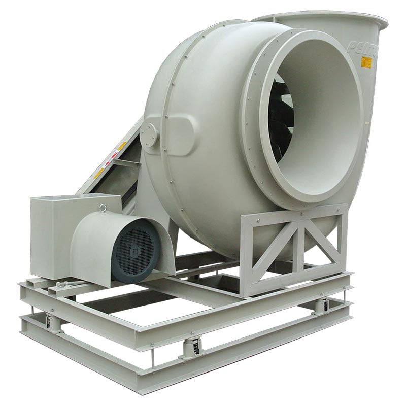
PP/FRP centrifugal blower for high-pressure industrial exhaust applications where a standard centrifugal fan cannot overcome the system resistance. While a centrifugal fan typically operates at 1,000-1,200 Pa, a centrifugal blower is designed for higher pressure duty — handling system resistances up to 2,500 Pa and beyond through a combination of higher impeller tip speed, multi-blade configuration, and scroll-type volute geometry optimized for pressure development rather than volume. The PP or FRP construction provides full corrosion resistance. Applications include: pushing exhaust through high-pressure-drop scrubbers, long duct runs with multiple fittings, systems with HEPA or carbon filter banks downstream of the fan, and multi-stage treatment trains requiring pressure to overcome sequential equipment losses.
| Application | High-pressure industrial exhaust — scrubber discharge, filter bank pressurization, long-distance duct transport, multi-stage treatment systems, applications where system resistance exceeds centrifugal fan capability |
| Material | PP volute + PP impeller (≤60degC); FRP volute + FRP impeller (≤80degC, higher strength) |
| Pressure range | 1,000-2,500+ Pa — higher pressure than standard centrifugal fan |
| Air volume | 500-15,000 m³/h standard; larger custom configurations |
| Impeller | Multi-blade PP injection-molded or FRP — designed for pressure, not volume; G6.3 balanced |
| Drive | Direct drive (standard) or belt-driven; 1,440 or 2,900 RPM |
| Motor | 0.75-15 kW; anti-corrosion coated housing |
| Lead time | 15-25 days |
Fan vs Blower: The Pressure Distinction
The terms are often used interchangeably, but in engineering practice, a fan and a blower are different machines optimized for different points on the pressure-volume curve:
- Fan = high volume, low-to-moderate pressure. A centrifugal fan (G1, G2) is designed to move large air volumes (2,000-80,000 m³/h) against moderate system resistance (500-1,200 Pa). The impeller has relatively few blades with large passages between them — optimizing for airflow with acceptable pressure development. The volute is sized to efficiently convert velocity to static pressure at the design airflow. This is the correct machine for most ventilation and general exhaust applications.
- Blower = moderate volume, high pressure. A centrifugal blower is designed to develop higher pressure (1,500-2,500+ Pa) at moderate air volumes (500-15,000 m³/h). The impeller typically has more blades with narrower passages — trading some airflow capacity for greater pressure development per stage. The volute geometry is tighter, designed to maximize pressure recovery at the expense of some flow capacity. This is the correct machine when the system includes high-resistance components downstream of the fan — HEPA filters (250-500 Pa when clean, up to 750 Pa at change-out), deep-bed carbon filters (300-600 Pa), or long duct runs with multiple elbows and fittings.
- Choosing the wrong machine wastes energy. A blower specified for a low-pressure application moves less air for the same power consumption. A fan specified for a high-pressure application stalls or operates far left on its curve — unstable, inefficient, and noisy. The correct machine is determined by the system resistance curve: calculate total pressure drop at design airflow, add 20% margin, and select the machine whose best efficiency point is near your operating point. Our PP Centrifugal Fan handles most general applications; the blower is for high-pressure duty.
Blower Applications: When System Resistance Drives the Decision
| Application | Typical System Resistance | Why Blower |
|---|---|---|
| Scrubber discharge to tall stack | 1,200-1,800 Pa | Scrubber outlet pressure + stack height static head + stack exit velocity, all downstream of the fan |
| Carbon filter bank pressurization | 800-1,500 Pa | Multi-bed carbon filters have high resistance that increases as carbon loads — blower has the pressure margin |
| HEPA filter exhaust (pharmaceutical, nuclear) | 1,000-1,800 Pa | HEPA banks at 250-500 Pa clean, plus pre-filters, ductwork, and stack; blower pressure handles end-of-life filter loading |
| Long-distance duct transport | 500-1,200 Pa in duct friction alone | Duct runs exceeding 100 meters with multiple elbows accumulate friction losses that exceed fan capability |
| Multi-stage treatment train | 1,500-2,500 Pa cumulative | Venturi scrubber (500-800 Pa) + packed bed scrubber (300-500 Pa) + mist eliminator (100-200 Pa) + carbon bed (400-600 Pa) + stack = 1,300-2,100 Pa before duct losses. A blower is required. |
Why Xicheng
16 years, 2600+ systems shipped worldwide. A blower operating at higher pressure experiences higher mechanical stress on the impeller, higher bearing loads, and higher air temperature rise from compression — all of which must be accounted for in the design:
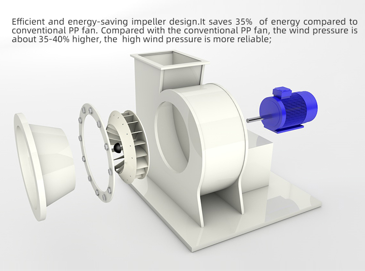
- Impeller designed for pressure, not just volume. Our centrifugal blower impellers use a multi-blade configuration with narrower flow passages than a standard fan impeller — each blade passage handles less airflow but contributes more pressure development. The result is a steeper fan curve: pressure rises more sharply as flow decreases, giving the blower better ability to push through increasing system resistance (such as filter loading over time) without stalling. The one-piece injection-molded PP construction means no blade-to-hub joints to fatigue under the higher cyclic stress of pressure operation.
- Scroll volute for pressure recovery. The volute geometry differs from a standard fan — the scroll profile is designed to maximize static pressure recovery from the high-velocity air leaving the impeller tips. The cut-off clearance is tighter, and the discharge diffuser section is longer, converting more velocity pressure to static pressure before the air enters the discharge duct. This geometry is why a blower looks different from a fan — the volute is proportionally larger relative to the impeller diameter.
- Temperature rise accounted for in material selection. Compressing air raises its temperature — the energy added by the impeller appears as heat. At 2,500 Pa pressure rise, the adiabatic temperature rise is approximately 2-3degC — negligible for material selection. But at higher pressures or when the inlet air is already warm (50-60degC), the discharge temperature can approach PP’s 60degC limit or FRP’s 80degC limit. We calculate the expected temperature rise and verify material compatibility at the discharge condition, not just the inlet condition.
Send your system resistance calculation and airflow requirements to xicheng023@outlook.com. We’ll verify whether a fan or blower is the correct machine and provide a performance curve. WhatsApp: +86 18927456906.
Core Advantages
- Higher Pressure Than Standard Centrifugal Fans: 1,000-2,500+ Pa vs 1,000-1,200 Pa — overcomes high-resistance downstream equipment that would stall a standard fan.
- Multi-Blade Impeller for Pressure Development: More blades, narrower passages — optimized for pressure, not just volume. Steeper fan curve handles increasing filter resistance.
- Full PP/FRP Corrosion Resistance: Same material options as our standard fans — PP ≤60degC, FRP ≤80degC. Chemical compatibility verified per application.
- One-Piece Injection-Molded Impeller, G6.3 Balanced: No blade joints to fatigue under the higher cyclic stress of pressure operation.
- Correctly Applied — Fan or Blower, Not Guessed: We verify your system resistance and recommend the right machine. No blower sold into fan-duty applications; no fan sold into blower-duty applications.
Key Specifications
| Model No. | XC-5H |
| Material | PP volute + PP impeller (≤60degC); FRP volute + FRP impeller (≤80degC) |
| Type | Centrifugal blower — high-pressure, multi-blade impeller |
| Pressure Range | 1,000-2,500+ Pa |
| Air Volume Range | 500-15,000 m³/h standard; larger custom |
| Impeller | Multi-blade PP injection-molded, F4-72 derivative, G6.3 balanced |
| Drive Type | Direct drive (standard) or belt-driven |
| Motor Power | 0.75-15 kW |
| Motor Speed | 1,440 or 2,900 RPM |
| Gas Temperature | PP: ≤60degC; FRP: ≤80degC (plus compression temperature rise) |
| Service Life | 8-10 Years |
| Brand / Origin | Xicheng / China |
Certifications and Compliance
- CE Certified – Centrifugal Blower
- RoHS Compliant – PP and FRP materials
- ISO 9001 – Quality Management System
- ISO 14001 – Environmental Management System
- SGS Tested – PP impeller, FRP mechanical properties, pressure testing, G6.3 balance
- Design Compliance – Blower designed to meet EU Industrial Emissions Directive (2010/75/EU); impeller balance per ISO 1940 G6.3
How to Order
- You send – Air volume, total system resistance breakdown (all equipment + ductwork), gas composition and temperature, altitude (affects air density and blower performance)
- We verify – Whether fan or blower is correct for your resistance; material compatibility with gas chemistry
- We select – Blower model, motor power, drive configuration, provide performance curve at your operating conditions
- You approve – Blower curve, motor specification, and pricing
- We build – 15-25 days. Impeller balanced, blower assembled, pressure-tested
Contact xicheng023@outlook.com or WhatsApp +86 18927456906 — application review and blower selection within 24 hours.
Complete Your System
- PP Centrifugal Fan – Standard fan for lower-pressure applications
- PP/FRP Negative Pressure Fan – Belt-driven for negative pressure upstream
- Wet Scrubber System – Matched scrubber for complete treatment
- Permanent Magnet VFD Fan – VFD energy-saving alternative
FAQ
How do I know if I need a fan or a blower?
Calculate your total system resistance at design airflow: sum the pressure drop across every component (duct friction, elbows, tees, dampers, scrubber, filters, stack) plus the velocity pressure at the stack exit. If the total is under 1,200 Pa, a centrifugal fan is typically sufficient. If over 1,200 Pa, a blower is likely needed. If over 2,500 Pa, contact us — you may need a multi-stage blower or a different machine type altogether. Send us your system resistance calculation and we’ll verify the correct machine selection.
Can a blower be used on the inlet side (negative pressure) of a system?
Yes, but the blower must be specified for negative pressure inlet conditions. The inlet air density is lower (due to lower absolute pressure), reducing the blower’s mass flow capacity and pressure development compared to the catalog curve measured at atmospheric inlet. We compensate for this in the selection — the blower will be physically larger than the catalog would suggest for the same airflow and pressure at atmospheric inlet. This is the same compensation applied to negative pressure fans (G3).
Does the blower require more maintenance than a standard fan?
The higher operating pressure means slightly higher bearing loads and slightly higher impeller stress — but within the design margins of the machine. Maintenance requirements are similar to a standard fan: annual bearing inspection and lubrication (if not sealed-for-life), belt tension check (if belt-driven), impeller inspection for chemical attack or erosion every 2-3 years. The PP/FRP construction eliminates the corrosion-related maintenance that steel units require (coating inspection, rust treatment, repainting).