
A scrubber room is the enclosed space inside an industrial plant where a packed bed wet scrubber and its support systems are installed. Searching for “scrubber room” online mostly returns advice about portable air scrubbers for houses; this guide is about a different subject — the facility work required to place an industrial packed bed scrubber tower, its recirculation pump, sump, controls, and access platform inside a building, and to give that room the utilities, drainage, ventilation, and chemical storage it needs. The mistake that costs the most is guessing clearance numbers and utility loads instead of building a project input list. This guide gives you that list: envelope and clearance reserves, maintenance access, drainage and containment, room ventilation, chemical storage, utility interfaces, lifting points, hazardous-area screening, and local code review points — ending in a Facilities Input Data Sheet you can send to your designer, contractor, and scrubber supplier.
Key Takeaways
- A scrubber room is the enclosed space that holds the packed bed scrubber, recirculation pump, sump, controls, and access platform. Plan it as a facilities input list, not as a clearance number you look up.
- Name the clearance reserves, then let the vendor drawing fix the sizes. Operating side, packing pull, lifting, and electrical service zones are your job to reserve; their dimensions come from the manufacturer’s drawings and your project.
- Size doors and aisles to the largest replaceable component, not the tower footprint. Packing, pump, impeller, and mist eliminator are the items that move through the room over the scrubber’s life.
- Collect blowdown and leaks, contain them, and discharge only under permit. Scrubber liquid holds captured pollutants and cannot go to a storm drain or public water body.
- Keep the room under negative pressure and treat air-change rate as a screening reference. Exhaust to the outdoors away from intakes; confirm rates with your local codes.
Scrubber Room Layout: Equipment Envelope and Clearance Reserves
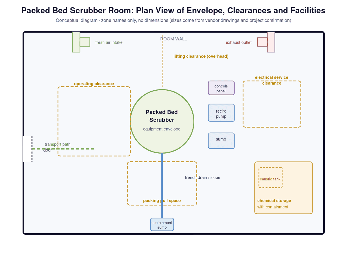
The layout of a scrubber room starts with the equipment envelope — the floor area and height the packed bed scrubber, its recirculation pump, sump, controls, and access platform actually occupy — plus the clearance zones you reserve around them for operation, packing pull, lifting, and electrical service. The direct answer is that the envelope defines what the room must contain, and the clearances define how people and parts move in, around, and over that equipment. You name the zones; the manufacturer’s drawings and your project confirm the dimensions, because a generic clearance value cannot be safe for every tower size and service.
What the Equipment Envelope Includes
A packed bed scrubber room is more than a footprint for the tower. The equipment envelope bundles the vessel itself, the inlet and outlet duct flanges that connect to the process, the recirculation pump that moves scrubbing liquor, the sump or integrated tank below the packing, the instrumentation (typically a pH loop, pressure gauges, and liquid level), and any access platform the vendor mounts on the tower. Each of these items takes floor space or overhead height, and the vendor’s general-arrangement drawing — not a rule-of-thumb — is the document that fixes the envelope.
The envelope also has a vertical component. Ductwork rises to the vessel’s inlet flange, the tower adds packing and demister height above the sump, and a top-mounted or side-mounted access point changes the overhead requirement. When you ask a scrubber supplier for the room layout, the two documents to request are the general-arrangement drawing with the envelope outline and the foundation/loading drawing, because the filled tower plus its liquid inventory is the load the floor slab must carry.
Vertical Tower vs Horizontal Scrubber: the Space Trade-Off
Packed bed scrubbers come in two geometric families, and the choice changes the room’s shape before any other decision is made. A vertical tower is compact on the floor but demands overhead: a typical vertical packed tower on industrial service needs roughly 15–40 ft (4.6–12.2 m) of clear height for the vessel, duct risers, and access — a figure that varies with gas flow and packing depth, which is why the vendor drawing sets the number. A horizontal scrubber is low-profile and needs far less ceiling, but it spreads across more floor area and places the access points at working height, so maintenance is often done without scaffolding.
The trade-off is therefore floor plan versus section height. A low-bay building or a retrofit inside an existing room with a modest ceiling pushes you toward a horizontal unit; a new building or a room with high-bay clearance rewards the vertical tower’s smaller footprint. State this choice to the vendor before requesting the envelope drawing, because the two configurations produce different floor footprints, duct routes, and maintenance access points.
Clearance Reserves You Name, Not Guess
Beyond the equipment envelope, a scrubber room needs four clearance zones that the facility owner names in the project input list, even though the dimensions come from the vendor or a qualified engineer. First, an operating side where an operator reaches the controls, pH instruments, sight glasses, and sample points. Second, a packing pull space — the area on the side or top of the tower where media is removed for inspection or replacement; the packing is the largest material that must come out of the vessel during the scrubber’s life. Third, a lifting clearance above any removable component, matched to the hoisting and lift-point section later in this guide. Fourth, an electrical service space in front of the control panel and motor starters, because an electrical enclosure that cannot be opened safely is a maintenance problem waiting to happen.
No generic clearance dimension appears in this guide, for a straightforward reason: a clearance adequate for a 10,000 cfm tower can be wrong for a 40,000 cfm tower, and the safe value depends on packing size, demister access, pump withdrawal, and local electrical code. Your job at this step is to reserve the zones on the layout and record them in the input data sheet; the vendor’s drawing then fixes the sizes, and the local authority having jurisdiction has the final say where codes apply.
Decision point: You can now draw a plan sketch of the room with the equipment envelope and the four clearance zones marked, and add to your input list the two vendor documents you still need: the general-arrangement drawing and the foundation loading drawing.
Maintenance Access, Doors and Transport Path
The direct answer is that the maintenance access plan is built around the largest replaceable component, because that is the item that must travel through the room over the scrubber’s life. If packing is pulled sideways, the aisle and door must accept the packing access height and the cart path; if a pump or impeller is removed, the path must accept that pump. Sizing the room to the tower footprint alone is the layout error that turns a routine packing replacement into a demolition job. Where an existing building constrains the room, the wet scrubber rebuild or retrofit assessment is the inspection-based way to decide whether the room or the scrubber should change.
Size Access to the Largest Replaceable Component
Start by listing what comes out of the scrubber during normal maintenance: packing media, the demister or mist eliminator, the recirculation pump (or its impeller and motor), level instruments, and spray nozzles. The packing is usually the largest item, and it is exchanged on a schedule tied to the service — corrosive or particulate-laden streams foul packing faster, which is why the room must anticipate packing pull at least once, not just at installation. Ask the vendor for the replacement-parts dimension sheet, and use the largest single piece to set the door opening, aisle width, and turning radius, not the tower shell.
Door, Aisle and Turning Clearance Basics
Equipment-room doors and aisles follow one principle: the opening must accept the largest component plus the carrying cart, with allowance for a 90-degree turn at the door and at any corridor corner. Door height matters as much as width, because a packing bundle that clears the width but not the header stops the job. When the transport path is long, mark the route on the plant layout, check overhead obstructions such as ductwork and sprinkler lines along the entire path, and record the clearances in the input data sheet for the contractor to verify.
Platforms, Ladders and Fall Protection
Where the scrubber’s access points sit above floor level, elevated platforms, ladders, and fall protection become a regulatory subject rather than a comfort issue. General-industry rules (OSHA 1910) require guardrails around elevated work surfaces — the standard top rail height is 42 inches (107 cm), with a tolerance of ±3 inches — and require fall protection where employees work at heights that present a fall hazard, typically 4 ft (1.2 m) or more above a lower level on general-industry platforms. Fixed ladders above 24 ft (7.3 m) also carry additional fall-protection requirements in the current rules. Confirm which edition and subpart applies at your site, because the local OSHA implementation governs the exact obligation. A scrubber room planned with the vendor’s platform drawing in hand, and with the platform, stair, and guardrail details reviewed against these rules, avoids retrofitting access after installation.
Decision point: You can now list the largest replaceable components with their dimensions from the vendor’s replacement-parts sheet, and state the door width, door height, aisle width, and platform/fall-protection requirements those items impose.
Drainage and Containment
The direct answer is that a scrubber room drains nothing directly to the environment: scrubber blowdown and chemical leaks are collected, contained, and discharged only under a permit that applies to your site. Wet scrubbing works by transferring pollutants from the gas stream into the scrubbing liquid, so the liquid that leaves the tower carries the captured contaminants, and facility planning must provide for where that liquid goes before the scrubber is purchased.
Blowdown and Bleed-Off Must Be Collected and Permitted
Scrubber blowdown is the liquor deliberately removed from the recirculation loop to control dissolved-salt concentration and prevent solids buildup in the packing, and it carries the pollutants the scrubber removed from the gas. University extension guidance for agricultural wet scrubbers states it plainly: scrubber effluent cannot be discharged to a stream, lake, or wetland and must be handled according to applicable rules — a principle that transfers directly to industrial rooms. The room therefore needs a drain and collection point for blowdown, a route to neutralization or a holding tank, and a decision about treatment versus off-site hauling that your permit defines. No generic discharge limit appears in this guide because the value is set by your local pre-treatment and wastewater permits, not by any article.
Secondary Containment for Chemical and Scrubber Liquid
Because the room handles reagent chemicals and concentrated scrubbing liquor, the floor plan should include secondary containment rather than relying on floor drains alone. The framework used for hazardous-waste container and tank systems is instructive even where your facility is not an RCRA site: containment must be able to hold at least the volume of the largest container, or 10% of the total volume of all containers, whichever is greater (40 CFR 267.195), and oil-storage secondary containment under the SPCC rule is sized to hold the largest tank plus freeboard for precipitation.
A scrubber room commonly applies the same idea with a concrete curb or dike around the chemical storage area and around the scrubber sump, with the contained volume checked against the largest tank on the pad. For a 25,000 cfm metal-finishing tower as an illustrative basis, the blowdown and pad-contained volume typically falls in the range of 15–20 gpm (57–76 L/min) — a planning figure, not a discharge value, that the vendor’s water balance and your permit set for your site.
Floor Drainage, Slope and Leak Routing
Room floors around the scrubber should slope toward a collection point, with a trench drain or floor drain routed to a containment sump rather than to a storm system, so that a leaking pump seal or a valve failure stays inside the room and reaches a place you can sample and pump out. A common industrial concrete-floor pitch for this purpose is on the order of 1/8 in per ft (about 1% slope, or 10 mm per meter), which is enough to move a spill toward the drain without making the surface uncomfortable to walk on. Locate the drain so a leak from the tower, pump, or chemical pad flows downhill into the containment volume. Record the drain outlet and the containment volume in the input data sheet, because your drainage permit and your AHJ both review this point.
Neutralize vs Haul Off: Decision Points
Whether scrubber blowdown is neutralized on site or trucked away is decided by concentration, volume, and your permits, and it is a planning input, not a retrofit afterthought. A caustic-scrubbed acid stream can often be neutralized and discharged to a permitted industrial sewer if the metal or salt load is acceptable; a stream with regulated metals, high salt, or low volume may go to a holding tank for off-site disposal. Determine the expected blowdown flow and composition from the vendor’s water-balance data and your process, then confirm with the local pre-treatment authority which route is permitted before the room is built.
Decision point: You can now specify the room’s drainage concept — blowdown collection point, containment volume around chemical storage and sump, floor slope and drain routing, and a neutralization-versus-hauling decision assigned to a responsible party.
Scrubber Room Ventilation: Negative Pressure and Exhaust Outlet Placement
The direct answer is that a scrubber room should be kept under negative pressure and exhausted to the outdoors, with the exhaust outlet placed so that it cannot pull back into the room’s fresh-air intake. Room ventilation exists to contain and remove fumes that escape from tank vents, pump seals, and open samples, and to prevent a chemical smell or a vapor hazard from migrating into adjacent work areas. The ventilation strategy is decided as part of the room layout, because it sets the location of the chemical storage area and the route of the exhaust ductwork.
Keep the Room Under Negative Pressure
Keeping the room slightly negative relative to surrounding spaces means air flows into the room from other areas rather than out of it, which is the direction that contains vapors. A planning target commonly used by ventilation designers is roughly 0.05–0.10 in w.c. of negative differential relative to the adjoining space — enough to pull air inward through doors and gaps while staying imperceptible in normal use, and a figure the HVAC designer sets from the room’s actual leak tightness. The authoritative ventilation-investigation guidance — the OSHA Technical Manual, Section III, Chapter 3 — describes this as the principle behind local exhaust and hood systems: the contaminant source is enclosed and air is exhausted away from the worker, with make-up air supplied from outside. For a scrubber room, that translates to exhaust at the level of likely vapor sources — tank vents, pump seals, sample points — and a tight room envelope so the negative pressure actually develops.
Exhaust Outlet Placement and Fresh-Air Intake Separation
Place the exhaust outlet on the room wall and the fresh-air intake so that the discharge cannot be drawn back into the intake — a separation that avoids recirculating the fumes you just removed. In practice this means the intake and exhaust are on opposite sides or ends of the room, with the exhaust outlet above grade and away from adjacent building openings. This is a layout input: record the intake and exhaust positions on the plan sketch before the HVAC ductwork is sized.
Air-Change Rate: A Screening Reference, Not an Acceptance Value
Air-change rate is the number of times per hour the room volume is replaced by ventilation air, and it is useful as a screening reference for sizing, but it is not an acceptance value that any article can set for your room. Common screening starting points for rooms with chemical storage fall in the range of roughly 6–12 air changes per hour, with the higher end for areas with strong acid or solvent fume sources. To translate that into a plan figure, run the arithmetic on your own room volume: for an illustrative footprint of 20 ft by 30 ft with a 20 ft ceiling, the volume is about 12,000 cu ft, and a 6–12 air-change screening range works out to roughly 1,200–2,400 cfm of room exhaust. Those figures are qualified references to confirm against your chemical list, your local codes, and your AHJ — the governing requirement at your site is the number that applies there.
Make-Up Air and Local Exhaust vs Dilution
Every cubic foot exhausted must be replaced by make-up air, and the choice between local exhaust at the source and general dilution ventilation follows the OSHA guidance: capture the contaminant at the source when the source is fixed and known, because it removes the vapor before it enters the room air, and use dilution only where sources are diffuse or local capture is not practical. A scrubber room usually applies both — local exhaust at tank vents and pump seals, plus a general room exhaust to catch fugitive vapors — with the balance set by the chemicals and the room geometry.
Freeze and Condensation Protection
In cold climates, the scrubbing-liquid lines and the sump are vulnerable to freezing, and warm humid exhaust can condense inside cold ductwork. Heat tracing or insulation on liquid lines and on the sump, and a room temperature held above 32 °F (0 °C) in occupied areas, are the practical protections; the same guidance that governs wet-scrubber installation applies to the room around the equipment. Note the local winter design temperature in the input data sheet — for a cold-climate site, a design ambient of −10 °F (−23 °C) is not unusual — so the contractor can confirm tracing and insulation requirements.
Decision point: You can now state the ventilation concept — negative-pressure room, intake and exhaust positions on the plan, a screening air-change range to confirm locally, and the local-exhaust points at tank vents and pump seals — and hand it to the HVAC designer with the chemical list.
Chemical Storage and Feed Interfaces
The direct answer is that reagent chemicals are stored in the scrubber room only where the room is laid out for it: a contained pad, segregated incompatible chemicals, and a feed system that can be isolated and flushed. The two reagents common on packed bed scrubbers are caustic soda (sodium hydroxide) for acid neutralization and, less often, acid for pH adjustment or particular chemistries, and their storage and feed are facility inputs, not vendor accessories.
Reagent Storage with Containment
Store reagent tanks on a curbed pad sized to contain the largest tank, apply the containment volume rules discussed in the drainage section, and keep incompatible chemicals separated — acids away from caustics and oxidizers, with the layout reviewed against the chemical compatibility guidance from your EHS authority and, where flammable liquids are present, the storage rules in NFPA standards. Reagent delivery often arrives in drums or in 1,000 L intermediate bulk containers (IBCs), so the transfer point needs the same drip containment and rinse connection as the pad. Note the storage temperature for caustic: 50% sodium hydroxide crystallizes near 54 °F (12 °C) (manufacturer data), so unheated rooms in cold climates must either heat the storage area or use a lower-concentration product, and that choice belongs in the input data sheet.
Feed Pumps, Metering and Transfer
Caustic is typically delivered by a metering or diaphragm pump into the scrubber’s recirculation loop, controlled by the pH setpoint, with an isolation valve and a flush connection so the line can be washed before maintenance. Plan the pump location on or near the containment pad, provide drip containment under the pump, and give the operator a way to rinse spills at the transfer point where drums or totes are connected. The feed interface is the point where the chemical supplier’s equipment and your room’s utilities meet, so list it as an interface in the data sheet.
Emergency flushing equipment belongs in the same layout, because the room handles concentrated corrosive reagent. Where the eyes or body of any person may be exposed to injurious corrosive materials, the general-industry rules require suitable facilities for quick drenching or flushing within the work area for immediate emergency use (29 CFR 1910.151(c)). The installation standard used in practice, ANSI/ISEA Z358.1, places a plumbed eyewash within 10 seconds’ travel of the hazard — commonly planned at roughly 55 ft (17 m) — and requires it to supply at least 0.4 gpm (1.5 L/min) of flushing fluid for a minimum of 15 minutes. Locate the eyewash at the reagent transfer point and the containment pad, protect it from freezing, and record it in the input data sheet as a room fixture.
Chemical Compatibility and Materials
The materials in the chemical path — storage tank, feed line, metering pump, and the scrubber’s wetted internals — must be compatible with the reagent at the concentration used. Polypropylene, CPVC, and fiberglass-reinforced plastic are common on caustic and acid services, with the exact grade selected from the manufacturer’s compatibility tables rather than assumed from the polymer family alone. Record the reagent, its concentration, and the feed materials in the input data sheet; this is also the point where a chemical recirculation pump is specified, and the pump supplier’s material recommendation belongs in the package.
Decision point: You can now list the reagents, their storage tank sizes and containment pad, the feed pump type and location, the flush/isolation points, and the material selections, and hand that list to the chemical and pump suppliers for confirmation.
Scrubber Room Utilities: Water, Power, Instrument Air and VFDs
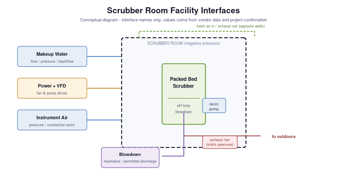
The direct answer is that a scrubber room needs four utility interfaces defined before construction: makeup water, electric power with variable-frequency drive for the fan and pumps, instrument air where the controls require it, and the fan’s static-pressure duty integrated with the scrubber’s pressure drop. None of these can be guessed from the room size alone; each is a project input whose value comes from the vendor’s design data and your site’s available services.
Makeup Water: Quality, Flow and Pressure
Wet scrubbers consume water continuously — water is lost to evaporation in the exhaust, to blowdown, and to the small amount carried out with the gas — and the makeup flow is a design input from the vendor’s water balance, not a number to guess from the room size. For a sense of scale, the blowdown portion of the worked example in this guide — a 25,000 cfm packed tower on metal-finishing exhaust — sits in the range of 15–20 gpm (57–76 L/min), and the makeup flow equals that blowdown plus evaporation. Those are illustrative planning figures that the vendor’s water balance replaces for your duty. The quality matters as much as the flow: hard water can drive scale on packing, and the required water quality follows from the vendor’s guidance for the recirculation loop. Supply the makeup water at the flow and pressure the vendor states, with a backflow prevention arrangement where the room ties into the plant potable system.
Power, VFD and Controls
The room’s electric load is set by the fan motor, the recirculation pump motor, the feed pumps, and the control panel. Fans and pumps on scrubber service commonly use variable-frequency drives so the operator can adjust flow and maintain the system curve as the packing loads; the VFD and motor sizing come from the fan and pump curves. Provide a dedicated circuit and a disconnect at the panel, and record the connected load and the required supply voltage in the input data sheet so the electrical designer can confirm the feeder. In North American installations the common supply is 460 VAC three-phase at 60 Hz for fan and pump motors, with 120 VAC single-phase for the control panel; confirm the site’s actual service voltage before ordering the drives, because a mismatch between the plant bus and the motor nameplate shows up only after installation.
Instrument Air and Compressed Air
Instrument air is needed where the scrubber uses pneumatically actuated valves or instruments; the pressure and flow demand is small but must exist before commissioning, or the control loop cannot be tested. If the plant has a compressed-air system, confirm the dew point and pressure at the scrubber location; if not, add a dedicated unit to the project scope. Record the instrument-air connection point and the required pressure on the data sheet.
Fan Static Pressure and System Integration
The exhaust fan must overcome the scrubber’s pressure drop plus the ductwork losses, and the pressure drop of a packed tower varies with packing depth and gas velocity. Packed-tower suppliers quote total pressure drop in a typical range of roughly 2–8 in w.c. for water-scrubber duty, with the exact value set by the vendor’s curve rather than by the room dimensions. Industrial scrubber suppliers describe this as a system integration issue: the fan, the tower, and the ductwork must be matched as one system, because an axial fan that is sensitive to pressure rise can stall if the system curve is wrong. Include the fan’s static-pressure requirement and the system curve in the input data sheet, and confirm the fan placement — inside the room or on the roof — because that choice affects the room’s noise, heat, and structural load.
Decision point: You can now list the four utility interfaces — makeup water (flow, pressure, quality, backflow), power (connected load, voltage, VFDs), instrument air (pressure, connection point), and fan duty (static pressure, system curve, placement) — and add them to the project input data sheet for the designer and the utility suppliers to confirm.
Hoisting and Maintenance Lift Points
The direct answer is that a scrubber room should provide lifting points sized to the heaviest replaceable component, with the load and the overhead clearance confirmed from the vendor’s drawings before the room is built. Packing, pump motors, and demister elements are heavy enough that manual handling is unsafe, and a beam, eyebolt, or portable gantry planned at the right position turns a two-day rigging job into a one-hour lift.
Lifting Points Sized to the Heaviest Replaceable Component
Identify the heaviest component that comes out of the scrubber — frequently the recirculation pump motor or a packed-bed access hatch assembly — and size the lifting point, beam, and rigging to that weight with an appropriate safety factor. Record the weight and the lifting-point location on the plan, and ask the vendor to confirm the service load for the designated lift points on the vessel itself, because not every nozzle or flange is a lifting point.
Order-of-magnitude weights help you start that conversation with the vendor. A recirculation pump on a mid-size packed tower commonly falls in the range of 150–400 lb, its motor 100–300 lb, and a full bed of packing media for a 25,000 cfm tower on the order of 1,500–3,000 lb depending on media type and bed volume. Chain hoists are commonly rated in steps such as 1,000, 2,000, and 5,000 lb, and the practical rule is to select a hoist at or above the heaviest packaged component, with a rigging safety factor — often a design factor of 2 on hoist capacity relative to the lifted load.
Overhead Clearance and Beam/Eyebolt Placement
The lift needs vertical clearance above the component’s removal path, which is why the lifting clearance in the layout section and the hoisting plan must be drawn together. Place the lifting point directly above the removal path so the load travels vertically rather than dragging across the floor, and confirm the overhead clearance against the rigging height. Where the room has no structural beam at the right position, a portable gantry rated for the load is the simpler plan and should be noted in the data sheet so floor space is reserved for it.
Plan the lift geometry against the vendor’s general-arrangement drawing rather than a rule of thumb. The rigging height of a chain hoist and its trolley, the lift point’s location above the removal path, and the component’s tallest dimension on the way out all have to fit inside the available headroom, so the clearance is a drawing check, not a number this guide can give you. Because a scrubber tower is usually installed with its pump and piping already in place, verify the removal path with the vendor — particularly whether the heaviest component travels out through an access hatch, over an adjacent duct, or past the fan casing — before the beam position is fixed.
| Replaceable component | Order-of-magnitude weight (illustrative) |
|---|---|
| Packing media bed, 25,000 cfm tower | 1,500–3,000 lb |
| Recirculation pump | 150–400 lb |
| Pump motor | 100–300 lb |
| Demister or access-hatch assembly | Confirm with vendor |
Decision point: You can now add the heaviest removable component’s weight, the lift-point location, the required overhead clearance, and the rigging method (beam, eyebolt, or gantry) to the input data sheet, with vendor confirmation of the vessel’s designated lift points.
Electrical Hazardous Area Classification
The direct answer is that most scrubber rooms on water and acid service are not classified hazardous (classified) locations, but the classification must be evaluated when the inlet gas can carry flammable vapor or solvent, and the decision is made by an electrical engineer under the applicable electrical code. This section gives you the screening framework; it does not replace the electrical engineer’s classification.
When a Scrubber Room Is Not a Classified Area
A scrubber room handling a typical industrial airstream — acids, caustic, water vapor — contains no flammable gas or vapor source under normal operation, and electrical equipment in it is selected for the corrosive environment rather than for a classified (hazardous) area. That is the common case, and it is why most wet scrubber installations use standard industrial motors and control panels with corrosion protection, not explosion-proof equipment.
When It Must Be Evaluated
If the process stream entering the scrubber can carry flammable gas or solvent vapor — for example, exhaust from a process that uses or emits solvents, or a gas stream with a lower explosive limit concern — the room’s electrical classification must be evaluated under the electrical code’s classification system (NEC Articles 500 through 506 and the equivalent NFPA standards), considering the vapor concentration, release sources, and ventilation.
The screening that emerges from that evaluation usually settles on the lowest applicable level. A vapor source present only under abnormal conditions points to a Class I, Division 2 (or Zone 2) location, while a flammable liquid stored with a flash point below 100 °F raises the same question for the storage area. Continuous ventilation that keeps vapor concentrations below 25% of the lower explosive limit is the usual engineering basis for confirming the lower classification, and the evaluation must consider the specific vapor — a common solvent such as acetone has a lower explosive limit of about 2.6% by volume in air. The classification is a professional determination: the input you make here is to flag the possibility in the data sheet so the electrical engineer performs the evaluation before equipment is specified.
Corrosive-Environment Equipment Selection
Even in a non-classified room, the atmosphere around a wet scrubber is humid and can carry traces of acid vapor, so motors, panels, and lighting are selected with an appropriate enclosure rating and corrosion-resistant finish rather than standard indoor gear. Ambient temperature inside an enclosed scrubber room depends on the tower and duct surface heat, commonly ranging from 40 to 104 °F (4 to 40 °C), which is within the rating band of standard industrial enclosures; the corrosive environment, not the temperature, is what drives the NEMA 4X or IP66 selection. Record the enclosure rating and corrosion finish requirement in the data sheet; the vendor’s standard package for scrubber service usually reflects this, but the room’s equipment selection should be confirmed against the actual environment.
| Inlet stream or storage | Classification outcome to verify |
|---|---|
| Water, acid, caustic vapor only | Nonclassified; corrosive-environment enclosures |
| Solvent vapor possible under abnormal conditions | Class I, Division 2 (or Zone 2) evaluation |
| Flammable liquid stored in the room | Storage area classified per adopted fire code |
Decision point: You can now state whether the inlet stream can carry flammable vapor, and if so, add “electrical classification evaluation required” to the project scope; in all cases, specify the corrosion-resistant enclosure rating for the room’s electrical equipment.
Local Code Review Points
The direct answer is that a scrubber room project is reviewed against building, fire, electrical, and wastewater requirements by the local authority having jurisdiction (AHJ), and your job is to assemble the documentation that makes that review possible. The review-point list below omits specific code citations because the applicable codes and editions vary by jurisdiction.
Building, Fire and Electrical Code Review Points
The AHJ review typically covers the building construction of the room, the fire-resistance and means-of-egress provisions where the room adjoins other occupancies, the electrical installation against the adopted electrical code, and the ventilation arrangement. Assemble the layout plan, the equipment envelope drawing, the hazardous-area screening result from the previous section, and the ventilation design for the reviewer. Where flammable liquids are stored, the fire code’s storage requirements apply, and the room layout should be confirmed against them before construction rather than after.
Drainage and Wastewater Permits
The drainage and blowdown route decided in the drainage section is a permit subject: the local wastewater or pre-treatment authority approves the discharge, and the containment design is reviewed where regulations require it. Gather the expected blowdown flow and composition from the vendor’s water-balance data and your process for the permit application, and confirm the neutralization or hauling route before the room is built. In the worked example of this guide, the planning blowdown sits at 15–20 gpm (57–76 L/min) — the quantity the permit application must state, along with the pH range and the pollutant concentrations expected from your process.
Documentation to Have Ready
The documentation that makes a scrubber room review efficient is short and specific: the P&ID or process flow of the scrubber system, the room layout with the envelope and clearance zones, the chemical list with concentrations and storage quantities, the blowdown and discharge characterization, and the vendor’s general-arrangement and loading drawings. Assemble these in the project folder before the review meeting, and record the AHJ’s name and the applicable codes on the input data sheet so the next stage of the project inherits the answer rather than re-deriving it.
| Document | What the reviewer checks | Record on the sheet |
|---|---|---|
| P&ID or process flow | Drainage route, vent connections, chemical feed | Blowdown 15–20 gpm (57–76 L/min), illustrative |
| Room layout | Envelope, access, clearance reserves | Exhaust 1,200–2,400 cfm screening figure |
| Chemical list | Quantities, concentrations, incompatibilities | Flash point below 100 °F where flammable liquids appear |
| Vendor general-arrangement and loading drawings | Lift points, service loads, utility connections | Drawing revision and date |
Decision point: You can now list the review points that apply to your jurisdiction — building, fire, electrical, drainage permits — and assemble the documentation set (P&ID, layout, chemical list, discharge characterization, vendor drawings) for the AHJ.
Project Input List: What to Send to Your Designer, Contractor and Supplier
The direct answer is that everything in this guide condenses into a single Facilities Input Data Sheet — a list of fields your designer, contractor, and scrubber supplier each need to confirm before detailed design starts. The sheet is the deliverable that turns the layout, drainage, ventilation, chemical, utility, lifting, and code sections into one hand-off document. This final section defines the fields, walks a complete worked example through the chain, and states clearly what the list cannot replace.
The Facilities Input Data Sheet Fields
A complete input data sheet records, at minimum: the site and building conditions (available floor area, ceiling height, ambient and winter design temperatures); the process and gas data the vendor needs (gas flow, inlet temperature and composition, pollutant load); the scrubber configuration chosen (vertical or horizontal, materials); the room layout decisions (envelope, clearance zones, door and aisle sizes, lift points); the drainage concept (blowdown route, containment volume, discharge destination); the ventilation concept (negative pressure, intake and exhaust positions, screening air-change range); the chemical list (reagent, concentration, storage quantity, feed interface); the utility requirements (makeup water, power and VFDs, instrument air, fan duty); the code and permit items (AHJ jurisdiction, applicable codes, permit route); and the items the vendor must provide (general-arrangement drawing, foundation loading, replacement-parts dimensions, designated lift-point loads). Each field is either a value you have confirmed or a question the recipient must answer, so the sheet doubles as the open-issues list.
Worked Example: a Metal-Finishing Packed Bed Scrubber Room
The example below is illustrative — a 25,000 cfm packed bed scrubber serving a metal-finishing acid-etch exhaust line — and every assumption is labeled so you can substitute your own numbers. The example walks the full decision chain and shows what a completed input sheet looks like.
Process and gas data. The exhaust is 25,000 cfm at 100 °F (38 °C) and roughly 50% relative humidity, containing acid vapor from the etch line; the vendor’s sizing output defines the tower diameter, packing depth, and pressure drop, and those values are the vendor’s, not this example’s.
Room layout. A vertical tower is chosen for the new building’s high-bay clearance. The vendor’s general-arrangement drawing fixes the envelope at approximately 10 ft by 12 ft (3.0 by 3.7 m) plus the recirculation pump, sump, and control panel; the operating-side zone, packing pull space, lifting clearance, and electrical service space are reserved per the layout section and confirmed against the drawing. A 7 ft (2.1 m) by 8 ft (2.4 m) door is assumed for the packing cart, subject to the replacement-parts dimension sheet.
Drainage and containment. Blowdown of about 15 gpm (57 L/min) is routed to a neutralization tank sized for the weekly blowdown volume; the chemical pad containment holds the largest reagent tank, and the floor slopes to a containment sump. The discharge route is subject to the local pre-treatment permit.
Ventilation. The room is held under negative pressure with the intake and exhaust on opposite walls; the screening air-change range of 6–12 per hour is confirmed against local codes. Local exhaust is provided at the caustic tank vent and the pump seals.
Chemicals. 50% caustic soda is stored in a 500-gallon (1,900 L) tank on the contained pad, heated to stay above the crystallization temperature (about 54 °F, 12 °C), with a metering pump feeding the pH loop.
Utilities. Makeup water is supplied at the vendor-stated flow and pressure with backflow prevention; the fan and pump motors are fed through VFDs on a dedicated 460 VAC at 60 Hz circuit; instrument air is provided at the control panel; and the fan static-pressure duty is confirmed against the tower’s pressure drop.
Lifting, electrical, and codes. The heaviest removable component (pump motor) sets the lift point and the rigging plan; the inlet stream carries no flammable vapor, so no classified-area evaluation is required, but corrosive-environment enclosure ratings are specified; and the building, electrical, and drainage reviews are scheduled with the local AHJ, with the documentation set assembled.
The completed sheet then lists each field with either the example value above or a confirmation request, and it is sent to the designer, contractor, and supplier as the basis for detailed design.
What This List Cannot Replace
The Facilities Input Data Sheet is a planning and hand-off tool, not a design. It does not replace scrubber sizing (tower diameter, packing height, liquid-to-gas ratio — the province of the gas scrubber selection and sizing work), it does not replace detailed structural and HVAC design, and it does not replace the AHJ’s approval of the final design. If a dimension in this example conflicts with your vendor’s drawing or your local code, the vendor drawing and the AHJ win. Use the sheet to start the conversation with a complete, confirmed input set — and to catch the missing interface before it becomes a construction change order.
Decision point: You can now assemble your own Facilities Input Data Sheet from the fields above, fill it with your site’s values, mark the open items for the designer, contractor, and scrubber supplier to confirm, and send it as the basis for detailed design of the scrubber room.
FAQ
Can a packed bed scrubber be installed outdoors instead of in an enclosed room?
Yes, an industrial packed bed scrubber can be installed outdoors, and outdoor installation removes the room-ventilation and building-code questions discussed in this guide. The trade-off is weather exposure: outdoor units need freeze protection on liquid lines and the sump once ambient temperature drops below 32 °F (0 °C), corrosion protection appropriate to the outdoor environment, and a layout that keeps the ductwork, fan, and controls accessible for maintenance. This guide focuses on the enclosed scrubber room; if your project is outdoor, carry over the envelope, access, drainage, and chemical containment decisions and review the weather-protection items with the vendor.
Who approves the final scrubber room design?
The local authority having jurisdiction (AHJ) approves the final design through the building, electrical, and fire reviews, and the wastewater authority approves the drainage and discharge route through the applicable permit. The vendor confirms the equipment envelope, foundation loads, and lift points; the designer of record confirms the structural and HVAC design; and the electrical engineer confirms the classification and equipment selection. The input data sheet from this guide is the document that assembles all of these answers in one place before the approvals begin.
Note: This guide provides engineering planning guidance for a scrubber room; clearance dimensions, ventilation rates, and discharge limits must be confirmed by the equipment vendor, the design team, and the local authority having jurisdiction for each specific project.
For sequencing the room project against the wider installation, operation, and maintenance timeline, the wet scrubber project lifecycle resources hub is the project map.


