
Key takeaways
- A wet scrubber installation is a sequenced acceptance process. From site readiness to commissioning and handover, every phase must pass before the next starts; a skipped phase is paid back as operating trouble after start-up.
- Verify the foundation and utilities before the scrubber arrives. Site readiness lags are the first source of installation delay.
- Leak-test the assembled system before energizing the pump. Sealing problems are cheapest to fix while the system is still empty.
- Confirm every instrument against the P&ID before start-up. Pressure differential, liquid flow rate, and pH are the data you judge performance by; an unverified instrument is no data at all.
- Commission against the design criteria and hand over with records. Performance acceptance records turn “installed” into “delivered.”
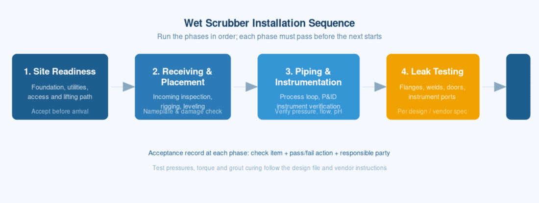
A packed-bed wet scrubber is usually lost to the schedule not by the scrubber itself but by installation work that was never checked: a foundation that was not verified, an instrument that was never calibrated, a leak found only after the pump was energized. This scrubber installation checklist walks the project through five phases — site readiness, receiving and placement, piping and instrumentation, leak testing, and commissioning and handover — with a check item and an acceptance action at every step. Work the phases in order; what you skip here becomes operating trouble later. The scope stops where an installation checklist cannot decide: duct installation, scrubber chemistry, and ongoing maintenance are covered on separate pages.
How to Use This Wet Scrubber Installation Checklist
Run the five phases in order and judge every check item against its stated source rather than against memory or habit. The sources that outrank a general checklist are the vendor drawings and manual, the P&ID, the project design file, and local codes; where a checklist line says “per design” or “per vendor,” that source decides the value.
Three parties carry the work, and the boundary between them is part of the plan.
| Party | Role during the installation |
|---|---|
| Owner project lead | Organizes receiving and inspection, accepts the record, controls the sign-off points |
| Contractor installation crew | Performs rigging, setting, piping, wiring, and testing; submits test records as evidence |
| Vendor field service | Supports the items named in the supply contract (typically leak testing and start-up); interprets design intent on open questions |
Two hard rules protect the schedule and the equipment. First, do not fill in the values the checklist leaves blank: leak test pressures, bolt torques, and grout curing times come from the design file, vendor instructions, and local code, and a wrong value is more dangerous than a missing one. Second, record every check as an item with an acceptance action and a responsible party, and do not move to the next phase until the current one has passed in writing.
To see the method in action, the worked example later in this checklist runs a 10,000 cfm packed-bed scrubber at a 300 gpm design circulation rate (example values, marked as such) and shows how the five phases gate one another. The acceptance phase then benchmarks removal against the EPA reference of above 90% for most absorbers, with the pollutant and the absorbent stated. Your next step is to assign the three roles in writing and to name the acceptance source for each check item, so no one has to decide a contested value on the day it matters.
Site Readiness — Foundation, Utilities and Access
Before any scrubber installation work starts on site, the site must answer one question: is the foundation, the utilities, and the lifting path ready to receive the equipment? Answer it with a checklist, because the equipment usually wins the race — the scrubber arrives on schedule whether the pad is cured or not.
The foundation and the service points are decided by two documents: the vendor’s full-operating (full-liquid) weight data and the local building code. Confirm the pad or steel frame is rated for that weight, the anchor bolt pattern matches the vendor foundation drawing, and the floor is level within the vendor tolerance before the truck arrives. Where the site has not yet settled how a wet scrubber removes gas-phase pollutants, settle that question before locking the foundation design.
The check table below lists the six items that gate the receiving phase. Two items are the usual delay sources: foundation load rating and the utility hookups, because both depend on data that must be requested from the vendor before arrival.
| Check item | Acceptance / action |
|---|---|
| Foundation load rating | Pad or steel frame rated for vendor full-operating weight; verified against local code |
| Anchor bolt pattern | Matches vendor foundation drawing; bolt size and projection per vendor |
| Floor level | Within vendor leveling tolerance (for the example tower, within 1/8 in. over 10 ft); shim or grout plan agreed before setting |
| Utility points | Water, drain, power, and compressed air reach the connection points; capacities per vendor manual |
| Lifting path | Clearance and floor rating for the rigging route from delivery point to final position |
| Maintenance access | Working space for nozzles, packing access, pump, and instruments per vendor layout |
Foundation verification
Verify the foundation against the vendor’s full-operating weight — the tower plus water, not the empty shipping weight — and confirm the pad or steel frame is designed for it under local code. A foundation sized for the empty vessel is the most expensive mistake this phase can make, because it cannot be corrected after the tower is filled. Match the anchor bolt pattern and size to the vendor drawing, and confirm the concrete has reached its specified strength or the grout has cured per the mix design before setting the vessel. For the worked example tower the numbers make the point: about 12,000 lb empty and 25,000 lb full of water and packing (example values), so a pad designed on the shipping weight would be short by more than half. The anchor bolts for that tower are torqued to 500 lb-ft per the vendor drawing (example).
Utility hookups: water, drains, power and compressed air
Four utility classes must reach the scrubber within the vendor’s recommended distance: water supply for makeup, a drain for blowdown and overflow, power for the circulation pump and any instrument panel, and compressed air where the system uses air-operated valves or instrument air. Confirm capacity and connection size against the vendor manual for each, and leave the mechanical and electrical isolation points where the maintenance plan can reach them. A missing drain connection is a commissioning problem in every case, because the sump must be filled, drained, and refilled during start-up. For the example tower, the vendor lists a 4 in. makeup water connection and a 2 in. blowdown drain (example); confirm both against the utility drawing before the pad is poured.
Lifting path and maintenance access
Plan the route from the delivery point to the final position before the equipment arrives: overhead clearance for the vessel and rigging, floor rating for the loaded lift, and a straight or minimally angled path. Set aside the working space the vendor layout requires — clear access to the packing access door, the spray header, the recirculation pump, and the instrument connections — because maintenance clearance decided after installation means disassembly inside the building.
Receiving and Placement — Incoming Inspection and Rigging
Receiving and placement answer two questions: is the equipment that arrived the equipment that was ordered, and is it now set in place without damage? Incoming inspection gates the acceptance signature; rigging and setting decide whether the internals survive the move. Most vendors supply a rigging drawing and lift-point marking; use them as the reference for this phase.
Unload and set only after the incoming inspection is complete and logged. Inspect before unloading where possible — a cracked flange or a bent lifting lug found at the dock is an insurance claim; the same damage found after setting is a site problem. The acceptance record should name the parts, list the damage, and carry the signatures of the driver, the contractor, and the owner representative.
| Check | Acceptance / action |
|---|---|
| Nameplate | Model, serial number, design pressure and temperature, empty and full weight match the order and the vendor documentation |
| Shipping damage | Dents, broken flanges, cracked sight glasses, and damaged nozzles logged with photos before unloading |
| Packing list | Every crate and part matches the packing list; missing or damaged items documented and signed |
| Lift points | Rigged only at the marked lifting lugs (for the example tower, a 30,000 lb rated lift); load path verified against the vendor rigging drawing |
| Leveling and anchoring | Vessel plumb and level; anchor bolts torqued per vendor; base grouted as specified |
| Internals | Packing, distributor, and mist eliminator intact and in place per the vendor drawing |
Incoming inspection: nameplate, shipping damage and packing list
Verify the nameplate against the purchase order before signing the delivery receipt: model, serial number, design pressure and temperature, and the empty and full operating weights. Photograph and log any shipping damage — dented shells, cracked flanges, damaged sight glasses, bent nozzles — and confirm the claim procedure with the carrier before the vessel is moved from the delivery point. Then work through the packing list part by part; a missing instrument or gasket set discovered at pre-start is a schedule problem, while the same gap found at receiving is a documentation problem.
Rigging and setting: lift points, leveling and anchoring
Rig the vessel only at the lifting lugs the vendor marked and rated; never sling around nozzles, the packing access door, or instrument connections. Confirm the rigging route and the crane or forklift capacity against the vendor rigging drawing before the first lift. Set the vessel on the prepared foundation, verify plumb and level, torque the anchor bolts to the vendor value, and complete any grouting as specified before the circulation loop is connected. For the example tower, the empty shell is about 12,000 lb and the loaded lift is 25,000 lb (example values); a crane or forklift rated at 30,000 lb keeps the lift inside its working capacity.
Internal condition: packing, distributor and mist eliminator
Open the access door once the vessel is level and confirm the internals survived transport and setting: packing in place and free of crushing, the liquid distributor level and unblocked, and the mist eliminator installed without gaps. This check is the reverse image of the vendor assembly drawing — every component the drawing shows should be present and correctly oriented. Note the condition in the record before the shell is closed, because the internals are not inspectable again without disassembly. For the example tower, the access door is 36 in. and opens the full packing section (example); use it to photograph the internals for the record. Decide the disposition of any damaged component — repair per vendor procedure, replace, or reject — before the shell is closed, because the record you sign names the equipment that enters the next phase.
Piping and Instrumentation — Connecting and Verifying the Loop
Connect the process and utility piping to the P&ID, then verify the instruments the operator will judge performance by — because an unverified instrument is no data at all. The P&ID is the acceptance reference for this phase: every line, valve, and instrument tag on the drawing must exist on the equipment before the loop is sealed.
The instrument list comes from the EPA monitoring framework for wet scrubbers: primary indicators (pressure differential, liquid flow rate, and outlet concentration or removal efficiency), secondary indicators (gas flow rate, neutralizing agent feed, and outlet gas temperature), and alternatives (scrubber liquid pH, scrubber liquid specific gravity, and makeup/blowdown rates). Verify each installed instrument against the P&ID tag, its range, and its calibration before the system is pressurized.
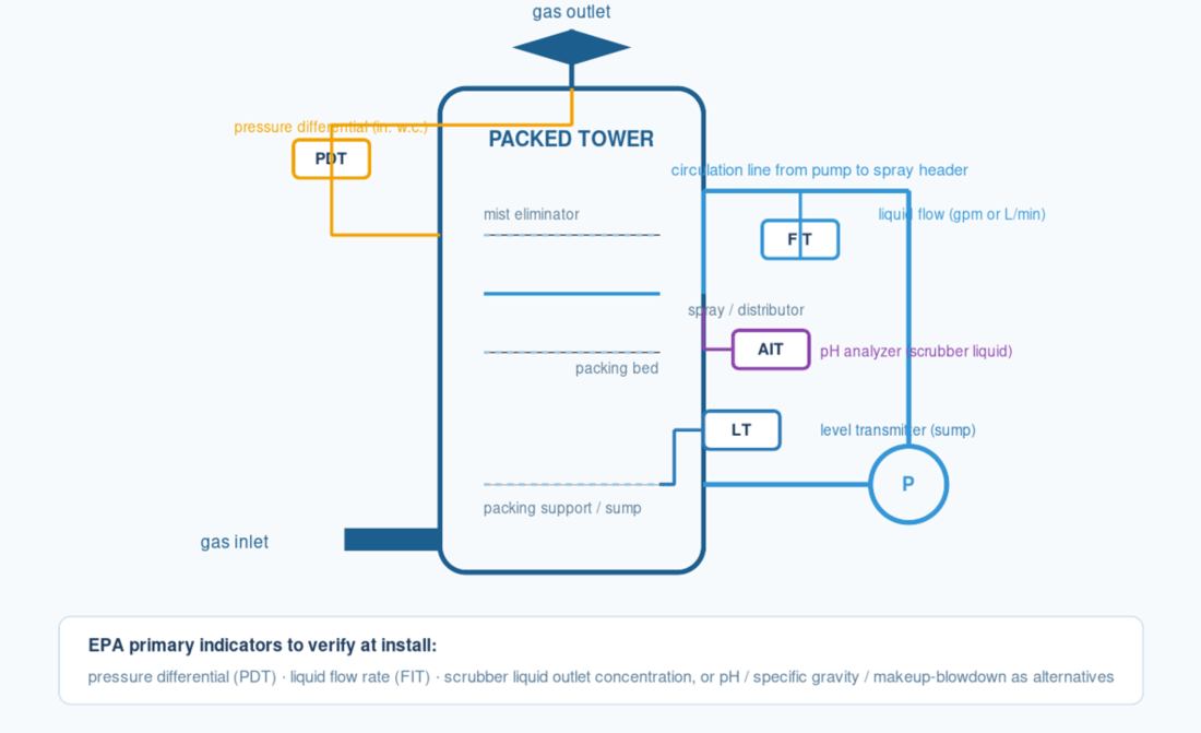
| EPA monitoring indicator | Install verification action |
|---|---|
| Pressure differential | Differential pressure taps across the packed bed installed and leak-free; transmitter calibrated |
| Liquid flow rate | Flow meter on the circulation line installed per vendor orientation; pump and meter match the design flow |
| Outlet concentration / removal efficiency | Sampling port installed per the applicable EPA method; analyzer or lab-connection provision in place |
| Gas flow rate | Duct connection and damper set; flow element installed where the P&ID specifies |
| Outlet gas temperature | Temperature element installed; panel readout matches the element |
| Neutralizing agent feed | Feed line, valve, and containment checked against the design; injection point per drawing |
| pH (alternative) | pH probe installed in the scrubber liquid loop; calibration solutions (pH 4 and pH 7 buffers) available |
| Specific gravity (alternative) | Density instrument installed; range set per vendor |
| Makeup / blowdown | Makeup valve and drain confirmed; level control provision checked |
Process and utility piping connections
Install the piping per the P&ID line list: flanges torqued to the vendor value, field welds made by qualified procedures, and pipe supports placed so the shell is not loaded by the piping weight. Include the vents and drains the drawing shows — a packed tower fills, circulates, and drains several times during start-up, and a missing drain turns a rinse step into a plumbing exercise. Confirm the connections between the scrubber, the pump, and the recirculation loop are exactly as drawn before tightening the last flange. For the example tower, the inlet duct is 24 in. and the nozzle count matches the vendor spray drawing (example); walk each connection once against the line list before the loop is sealed.
Instrument verification against the P&ID
Walk the P&ID instrument by instrument. For the primary indicators, confirm the pressure differential taps are installed across the packed bed, the flow meter sits in the circulation line in the orientation the manufacturer specifies, and the outlet sampling port follows the applicable EPA method. For the alternatives, check the pH probe position in the liquid loop and the makeup–blowdown arrangement. Every transmitter range must match the design values, and every reading must reach the control panel or recorder. For the example tower — a 10,000 cfm packed-bed scrubber with a 300 gpm circulation loop (example) — the pH alternative needs calibration buffers at pH 4 and pH 7 on hand before the probe is commissioned.
Electrical and control checks
Verify the control panel wiring against the electrical drawings, then confirm the interlocks that protect the equipment: pump low-flow or low-level protection, fan-to-pump sequencing where the design specifies it, and alarms on the parameters that matter. Check rotation direction on the pump and any fan before coupling or belt tension is completed. This is the last phase where an electrical error is cheap to fix; after the system is sealed and filled, the same error is a start-up abort. For the example tower the circulation pump is a 480 VAC, 20 kW unit (example); confirm rotation direction and panel draw before coupling. Use this phase to determine what the operator will trust later: every indicator that reaches the panel is data you can rely on, and every one that does not is a question to resolve before the loop is sealed.
Leak Testing — What to Check Before Energizing
Leak-test the assembled system before energizing the pump. The test answers one question: is the closed loop — vessel, flanges, welds, access doors, and instrument ports — tight at the test pressure the design specifies? Run it while the system is still empty, because every leak is cheapest to find before the internals are wet and the pump is running.
The check points below are where leaks appear first: every flanged joint, every field weld, and every opening that was closed after the internals check. Match the marked points on the vessel to the drawing, and log the result of each one rather than a single pass-or-fail verdict for the system.
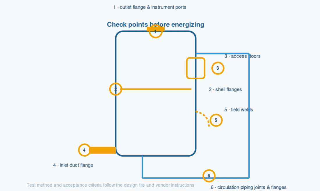
| Check point | What to verify |
|---|---|
| Outlet flange and instrument ports | Flange faces clean, gaskets seated, bolts torqued; ports capped or connected |
| Shell flanges | Bolted per the vendor value; no visible gaps or stress marks |
| Access doors | Gaskets in place and door hardware torqued; closed before pressurizing |
| Inlet duct flange | Flange match with the ductwork; sealing per the duct standard that applies |
| Field welds | Completed by qualified procedures; visually inspected before the test |
| Circulation piping joints and flanges | Pump suction and discharge connections verified tight |
What the test covers
The wet scrubber leak test covers every joint that closes the process loop: the flanges on the gas inlet and outlet, the shell flanges, the access doors, the field welds made during installation, the instrument ports and caps, and the circulation piping joints between the tower, the pump, and the recirculation line. Utility connections to water, drain, and compressed air are tested with their own loops where the vendor requires it. The point of the list is scope discipline — a system that passes a test of the vessel alone can still leak at the pump suction flange the day start-up begins.
How to run and judge the test
Run the test and judge the results per the design file and vendor instructions; the test medium, pressure, and hold time are set by the design, not chosen at the job site. Record the test parameters — medium, pressure, duration, ambient conditions — and the result of every check point. If a joint fails, mark it, repair it under the same procedure used for the original joint, and retest before moving on. Never release a failed point into the next phase with a verbal “it will be fine”; the record is the evidence the acceptance signature is based on.
For the example tower the vendor specifies a test pressure of 20,000 Pa (about 3 psi) held for 30 min, with the differential pressure gauges ranged to 6 in. w.c. (example values); the design for your vessel governs. Before you sign the leak test record, confirm that every marked check point has a line in the log — the signature is a statement that the list is complete, not that the system is perfect.
Pre-Start Checks and Commissioning
Pre-start checks and commissioning turn the assembled scrubber installation into an operating system: confirm the fill, clean and test the loop, start under controlled conditions, and accept performance against the design criteria. The pre-start checklist below is the last gate before the pump runs continuously, and it is also where the commissioning record begins.
Pre-start checklist
Confirm the items that commissioning depends on, in order: packing loaded to the drawing level, the circulation line flushed free of debris, the pump and spray nozzles tested with clean water, and the mist eliminator confirmed dry and correctly seated. Verify the sump fills and the level control responds, and confirm every instrument reading is live on the panel before the pump is started. Each line is a gate; a pump started with debris in the circulation line becomes a pump with a plugged nozzle.
| Pre-start item | Acceptance / action |
|---|---|
| Packing load | Packing filled to the design level, free of debris and voids |
| Circulation line flush | Loop flushed with clean water at the 300 gpm design rate (example); strainers and drains clear |
| Pump and nozzles | Pump primed, rotation confirmed, spray pattern verified with clean water |
| Mist eliminator | Dry, seated, and sealed per the vendor drawing |
| Sump and level control | Sump fills to operating level; level control responds |
| Instruments live | Pressure differential, flow, pH, and level readings reach the panel |
Start-up sequence
Bring the system up in controlled steps rather than full-load from the first start — the staged approach that vendor field-service guides describe for pre-start verification. Fill the sump and establish water circulation first; confirm the pump holds pressure and the spray pattern covers the bed before any gas is introduced. Then start the gas flow at a reduced rate and bring it toward the design gas flow while watching the parameters that move first: the differential pressure across the bed and the outlet gas temperature. Adjust neutralizing agent feed as the design specifies, and log the readings at each step so a later change can be compared against a baseline. For the example tower, the step-up ends at the design 10,000 cfm gas flow and 300 gpm circulation (example values), with each stage held for 15 min and logged before the next.
Performance acceptance against design criteria
Accept the scrubber against the primary EPA indicators — pressure differential, liquid flow rate, and outlet concentration or removal efficiency — compared with the design values and the vendor guarantee. The acceptance table below is the performance gate: each parameter is judged against a stated basis, and the accepted values become the operating baseline.
| Performance parameter | Acceptance basis |
|---|---|
| Pressure differential | Within the design range at the design gas flow; recorded as the operating baseline |
| Liquid flow rate | Matches the design circulation rate with the pump at design conditions |
| Outlet concentration / removal efficiency | Meets the vendor-guaranteed removal efficiency; as an industry reference, most absorbers remove above 90% depending on the pollutant and the absorbent (EPA) |
Sign the commissioning record with the owner, contractor, and vendor signatures before handover, and keep the accepted values with the operating manual — they are the baseline every future inspection and every future troubleshooting session starts from. Use that baseline to set your next step: lock the acceptance values into the operating manual before the vendor leaves the site, so the first quarterly check compares against a recorded start.
Installation Mistakes That Show Up After Start-Up
Most operating problems on a wet scrubber trace back to an install-phase decision, which means the checklist can prevent them. EPA lists air inleakage, poor liquid distribution, line pluggage, and scaling among the common problems that appear when pressure differential, liquid flow, and gas flow are not kept constant; each one maps to a check that was skipped, not to bad luck. The cost of a skipped check is measurable against the EPA benchmark: a scrubber designed to remove above 90% can drift below that number on a running day when an unsealed joint dilutes the outlet stream. In the 10,000 cfm example above, a nozzle plugged by construction debris traced back to a clean-water run that was skipped; a 30 min flush at pre-start would have caught it (example schedule).
The table pairs each problem with its install-phase cause and the countermeasure that closes it. Use it as a second pass over the five phases — a problem here is the reason a check there exists.
| Problem after start-up | Install-phase cause | Countermeasure |
|---|---|---|
| Air inleakage | Duct or flange joints not sealed; access door hardware not torqued | Complete the leak test and retest failed joints before energizing |
| Poor liquid distribution | Distributor not level, plugged by debris, or damaged during setting | Verify the distributor level and clear during the internal condition check; confirm spray pattern at pre-start |
| Scaling and pluggage | Water chemistry combined with an incomplete blowdown or drain connection | Confirm makeup, drain, and blowdown connections per the P&ID before filling |
| Low liquid flow | Pump not primed, suction strainer blocked, or nozzle plugged by debris | Flush the circulation line, confirm pump rotation, and test nozzles with clean water at pre-start |
| Tray or packing damage | Internals damaged during rigging or covered by debris | Inspect internals during receiving, before the shell is closed |
Air inleakage
Air entering the gas path at an unsealed joint lowers the concentration reaching the scrubber and distorts the flow the instrument reads. The install-phase causes are the joints the leak test covers: duct flanges, access doors, and instrument ports that were closed but never verified. Fix them at the leak test with a retest, not after start-up — an inleakage hunt on a running system costs far more than the retest of a marked joint.
Poor liquid distribution
A scrubber performs as its liquid distribution does: a distributor that is not level, partially plugged, or damaged during setting starves part of the bed and channels the gas around it. The countermeasure sits in two phases — confirm the distributor is level and clear during the internal condition check, and verify the spray pattern with clean water at pre-start. If the pattern is uneven at pre-start, the cause is still cheap to correct; after months of service it becomes a packing replacement.
Scaling and pluggage
Scaling and pluggage are water-chemistry problems with an installation footprint: the makeup, drain, and blowdown connections that control concentration must exist and be complete before the system fills. Confirm them against the P&ID during the piping phase, and flush the lines during pre-start so the first fill does not carry construction debris into the packing. A scrubber designed to bleed and drain can still scale if the blowdown line was never connected. Before you close the piping phase, walk the three connections — makeup, drain, blowdown — one final time against the P&ID; that 30 min walk is the cheapest scaling insurance in the project.
Worked Example — A Packed-Bed Scrubber Installation in Ten Weeks
The schedule below is an illustrative example built from the five phases, with example values chosen to show the pattern — not a description of a XICHENG project and not a promise about your schedule. Real durations depend on project scale, vendor lead times, site conditions, and inspection outcomes; treat the phase logic as the model, not the week numbers.
Assume a packed-bed scrubber sized for a process exhaust gas flow of about 10,000 cfm (example), with a design circulation rate of about 300 gpm (example) — roughly 30 gal per 1,000 acfm of gas — a 36 in. packed bed, a 24 in. inlet duct, and a full-operating weight near 25,000 lb against an empty shell of about 12,000 lb (example values). The leak test runs at 20,000 Pa for 30 min (example), and the circulation pump is a 480 VAC, 20 kW unit (example); the worked timeline below assumes these inputs. The installation runs ten weeks from the site-readiness audit to the commissioning signature, and every phase handoff carries a written acceptance record.
| Phase | Weeks (example) | Acceptance record produced |
|---|---|---|
| Site Readiness | 1–2 | Foundation verified against full-operating weight; utilities at connection points |
| Receiving & Placement | 3–4 | Incoming inspection passed; vessel set, leveled, anchored, grouted |
| Piping & Instrumentation | 5–6 | P&ID walk-down complete; instruments calibrated; electrical checks signed |
| Leak Testing | 7 | All check points tight at the design test pressure; failed joints retested |
| Pre-Start Checks | 8 | Packing loaded, line flushed, pump and nozzles tested, instruments live |
| Commissioning & Handover | 9–10 | Step-up start; performance accepted against design; records signed |
The handover pack is the asset the owner keeps, and each record in it maps to the phase that produced it. A complete pack makes the next phase of ownership — operations and maintenance — start from measured data instead of memory.
| Handover record | Contents |
|---|---|
| Incoming inspection record | Nameplate data, damage log, packing list sign-off |
| Foundation and setting record | Level check, anchor torque, grout sign-off |
| P&ID walk-down | Every line, valve, and instrument tag confirmed; calibration certificates |
| Leak test record | Medium, pressure, duration, per-check-point results, retests |
| Pre-start checklist | Filled and signed, with instrument readings |
| Commissioning record | Start-up log, accepted performance values, operating baseline, signatures |
The same five-phase sequence applies whether the vessel is this 10,000-cfm packed tower (example) or a smaller spray tower; the scrubber installation discipline is the ordering of the acceptance gates, not the equipment size. Decide the phase order and the record format once, and every future project — new build, rebuild, or retrofit — reuses the same gates.
FAQ
How long does a wet scrubber installation take?
A scrubber installation takes as long as its critical path allows. In the example project above the sequence ran ten weeks, but the real drivers are the foundation and grout curing, the vendor’s delivery schedule, the site crew availability, and how cleanly the inspection phases pass. The phase logic — readiness before receiving, sealing before start-up — compresses or stretches the schedule; the acceptance gates are not the place the schedule should be shortened.
What is the leak test pressure?
The leak test pressure is set by the design file and the vendor instructions for that vessel, not by a general rule. Test pressure depends on the design pressure rating, the materials, and the service, so this checklist deliberately leaves the value blank. Ask the vendor for the specified test medium, pressure, and hold time before the test is scheduled.
Who should perform pre-start checks?
Pre-start checks are a three-party activity: the contractor executes the items, the vendor’s field service supports the items named in the supply contract — typically the leak test and the first start — and the owner representative confirms and signs the record. Set that split in writing before the pre-start week, because the checkpoints need the right people at the panel and at the pump.
When is the first maintenance inspection after installation?
The first maintenance inspection is scheduled as part of handover, not invented later. The commissioning record and the vendor manual define the inspection interval and the items to check; planning the maintenance schedule from measured operating data is the subject of a separate maintenance guide. Set the maintenance plan at handover so the warranty terms and the inspection calendar start from the same date.
Final Steps and Equipment Support
An installation is complete when the acceptance records are signed and the operating baseline is recorded, not when the last bolt is tightened. For a scrubber installation, the data package that crosses the line with the signature carries the value: vendor drawings, the P&ID as installed, the operating manual, the test records, and the spare-parts list. These files are the reference for every future inspection, repair, and expansion. For the 10,000 cfm example above, that pack includes the leak test record with its 30 min hold, the calibration certificates behind the flow and pH readings, and the commissioning record with the accepted removal efficiency benchmarked against the EPA reference of above 90%. The table below maps each record to the number that defines it, so the pack can be checked complete before the signature.
| Handover record | The number that defines it |
|---|---|
| Leak test record | 20,000 Pa test pressure held for 30 min; per-check-point results and retests |
| Calibration certificates | Flow meter certified at the 300 gpm design rate; pH buffers at pH 4 and pH 7; transmitter ranges listed |
| Commissioning record | Step-up log to 10,000 cfm; accepted removal compared with the 90% EPA reference |
| As-built P&ID and vendor drawings | Every instrument tag confirmed; revisions marked and dated |
When the next step is equipment rather than installation — a new packed-bed scrubber for a process that has outgrown the current unit, replacement packing or internals, or a spray-tower configuration for a different duty — the equipment pages list the configurations, materials, and specification inputs. For scrubbers that run on caustic chemistry, the caustic scrubber installation and operation page covers the chemical operating side that this checklist intentionally leaves out. Before you close the project, decide who keeps the signed records and where the spare-parts list lives, so the handover does not end at the signature.
An installation also lands in a space, and the room around the vessel needs to be planned before it is built: pull space for packing and media replacement, drainage and secondary containment for the blowdown and chemical areas, and room ventilation for the fan and ducting. To turn those requirements into a facilities input list you can send to the designer, see our scrubber room layout and utility requirements guide.
For the route beyond commissioning — operation, maintenance, and the eventual rebuild or replacement decision — the wet scrubber project lifecycle map ties the installation phase to the rest of the system’s life.


