
Dust-producing stations rarely need a dust collector that is merely “safer”. They need one that matches the dust standing in front of the engineer. Two mistakes drive most bad purchases: treating a wet dust collector as a filter that catches everything, and comparing supplier quotations by a single efficiency number with no size band, airflow or pressure drop attached to it. This guide answers the question behind the search, how does a wet dust collector work, by following one chain of decisions: the capture mechanisms and the particle sizes they reach, the situations where wet collection is the wrong answer, the five designs used for dust, a selection table driven by your dust condition, and what leaves the unit as bleed water and sludge. You finish with a judgement table and an RFQ input list.
Key Takeaways
- A wet dust collector is a particulate scrubber, not a filter. Understanding how does a wet dust collector work starts with the size band it reaches, not with tank volume.
- Efficiency is bought with pressure drop. The same design returns different numbers at different energy input.
- The fines decide the outcome. Submicron duty belongs to a high-energy venturi or to dry filtration, not to a spray tower.
- Bleed and sludge are operating costs. Suspended and dissolved solids reach a ceiling, and the residue still has to be classified.
- Metal dust and water is a compatibility question. It is settled by the site’s dust hazard analysis, not by this page.
What a Wet Dust Collector Does
Buying a dust collector starts with reading the device for what it is: a contract between a dust cloud and a water surface. What is a wet dust collector? It is an air pollution control device that removes particulate from an exhaust stream by bringing that stream into contact with liquid, usually water, and then separating the loaded liquid from the cleaned gas. Nothing is destroyed in the process. Dust leaves the air stream and enters a liquid phase that has to be managed for as long as the unit runs.
A wet dust collector is a particulate scrubber, not a filter
A wet dust collector is a particulate scrubber: it uses liquid contact and relative velocity to move particles out of an air stream instead of trapping them on a medium. Media filtration builds a cake and blocks particles; scrubbing forces particles onto droplets, films and wetted surfaces, and then removes the loaded liquid.
That difference sets both the maintenance list and the failure mode. A scrubber has no bags to replace, but it has nozzles, a pump, a sump and a bleed line that decide whether it keeps working, and its capture falls with particle size in a way that a media filter’s does not.
Three jobs one unit has to do at the same time
Every unit performs three tasks at once: contact the dust with liquid, separate the loaded liquid from the gas, and hold the captured solids somewhere until they are removed. Quotations usually describe the first task and leave the other two implicit.
The consequence shows up in operation. Strong contact with weak droplet separation carries water and dissolved solids downstream; weak sump management recycles a slurry that eventually plugs nozzles and blinds trays.
Where the collector ends and the rest of the system begins
Treat the collector as a package rather than as a vessel: the hood and ducting deliver the dust, the fan supplies the energy, the water circuit feeds and bleeds the unit, and the residue route takes the sludge away. A design that ignores any one of those can be geometrically correct and still fail in the room.
That boundary is the first thing to establish before comparing hardware. Airflow at the capture point, dust loading, available water and the disposal route sit outside the vessel but inside the delivered result.
With the three jobs and the package boundary fixed, you can decide what a proposal has priced — the vessel, the water circuit and the residue route — instead of reading the vessel drawing alone.
How Does a Wet Dust Collector Work? The Capture Step
The wet dust collector working principle reduces to one idea: a particle is captured only after it stops following the gas around a water surface. How do wet dust collectors work in practice? The gas is accelerated past spray droplets, wetted plates or films, particles with enough inertia leave the flow lines and strike the liquid, the loaded liquid drains to a sump, and the gas passes a droplet separator before it leaves the unit. Nothing in that sequence depends on the size of the water tank.
Dust is caught when it stops following the air (impaction, interception, diffusion)
Dust leaves the gas when the path forces particles off the flow lines and onto a liquid surface, and three routes do that work: inertial impaction, interception and Brownian diffusion. Condensation and electrostatic capture appear far less often, and most wet designs for dust rely almost entirely on impaction. The band each route covers, and what it means for a tender, is set out in the table below. U.S. EPA’s cost manual chapter for particulate wet scrubbers carries the same bands and states the diffusion limit differently in a second section, so read it as an order of magnitude rather than a threshold (EPA wet scrubbers for particulate matter).
The mechanism mix explains why the fine end is the weak point. A design built for inertial impaction separates particles by mass, so particles below roughly 1 µm slip past the capture zone unless the unit buys extra energy, residence time or droplet surface area.
The size band decides what your collector can reach
What size particles can a wet dust collector capture? The answer is a band rather than a single figure, and it follows the capture route that dominates in a given design. The table below turns the mechanism set into procurement language.
| Capture route | Size band it covers | What it means for your tender |
|---|---|---|
| Inertial impaction | Particles generally larger than about 10 µm | The dominant route in most dust designs; specify the velocity and the pressure drop, not the tank size |
| Interception | Roughly 1.0–0.1 µm | Keeps the middle band in play where gas passes close to a droplet surface |
| Brownian diffusion | Most significant below 0.5 µm | Small particles wander into the liquid; capture depends on residence time and fine droplets, not on water volume |
| Condensation and electrostatic capture | Used far less often | Treat as add-ons; a quotation should not rest on them alone |
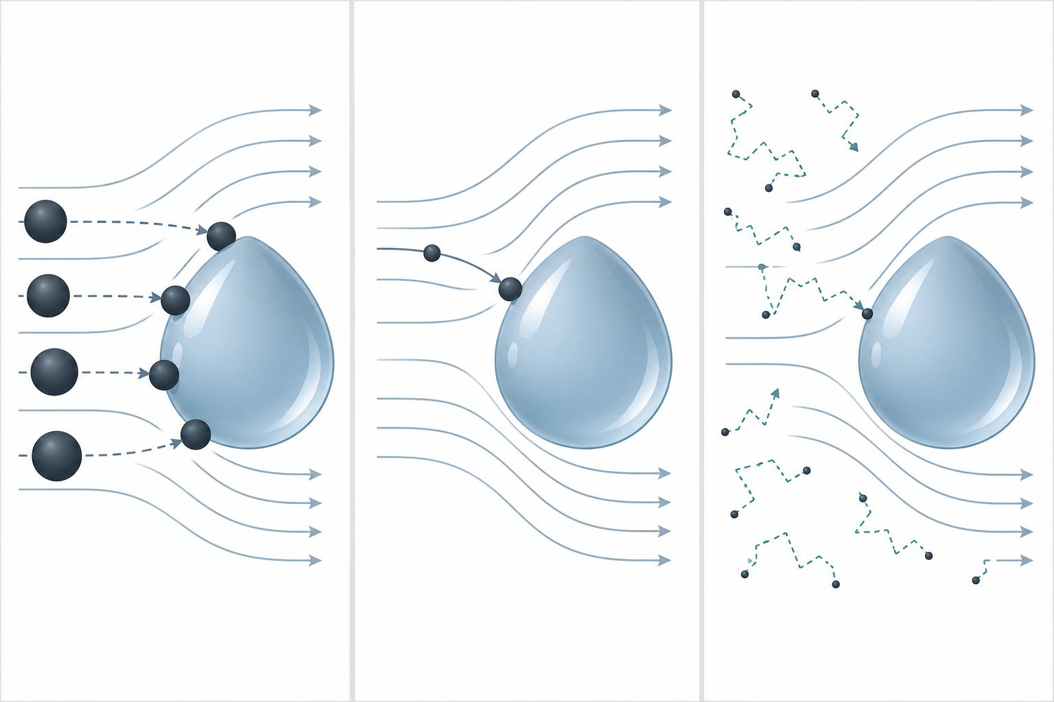
Read the band before the submission. A design that relies on impaction meets its test on the coarse fraction and loses the fine fraction, and adding water volume does not change that, because the missing ingredients are velocity and droplet surface area.
Efficiency is bought with pressure drop, not with the name of the design
Collection performance is bought with energy, and the price is paid as pressure drop and liquid-to-gas ratio. Venturi-type designs run between 10 and 80 in w.c., and above about 45 in w.c. the efficiency gain of a conventional venturi design is not significant; a venturi works at an optimal liquid-to-gas ratio of 7–10 gal per 1,000 ft³, where more liquid buys no further gain.
Supplier figures for wet dust collection range from capture at about 10 µm to 99.9% at 0.5 µm. Those numbers cannot describe the same duty, because none of them travels with an airflow, a particle size distribution or a pressure drop. No middle value is substituted here. An efficiency figure belongs in a quotation only alongside the dust size distribution, the pressure drop and the energy input it was measured at.
With the capture route, the size band and the pressure drop connected, you can screen a quotation on the numbers behind its efficiency claim instead of on the claim itself.
Where Wet Dust Collection Is the Wrong Answer
Knowing when to use a wet dust collector is easier once the conditions that rule it out are on the table, and four conditions settle the question before any design is compared. None of them is about a badly built unit. Each describes a duty or a site that asks water to do something it cannot do.
The fine end: fumes, condensed mist and submicron smoke
A stream whose load is fume, condensed metal oxide or smoke rather than dust from mechanical working has to be treated as a submicron-dominated duty. That is the band below 0.5 µm where diffusion does most of the capture work, and it sits below the size band that impaction and the pressure drop of a spray tower or tray unit are built for. Measure the size distribution before accepting any efficiency claim for that duty.
Choosing wet collection for that stream means buying pressure drop to recover part of the load. A high-energy venturi reaches into the submicron band that a spray tower cannot, and it does so at far higher energy. Where a permit limit rests on the submicron fraction, one wet stage rarely closes it.
Metal dust and water is a compatibility question, not a default
Water is not automatically the safe answer for metal dust, because compatibility varies with the material and the process. Combustible dust suspended in air can explode under specific conditions, and metals including aluminium, chromium, iron, magnesium and zinc can explode in dust form even where the solid metal does not burn readily; OSHA’s combustible dust topic page records 281 incidents, 119 deaths and 718 injuries in CSB data covering 1980 to 2005 (combustible dust hazards). Whether wet collection is acceptable for a specific metal dust is a conclusion of the site’s dust hazard analysis, not an assumption drawn from the material name. Approval follows a separate track with its own rulebook: OSHA’s combustible dust standards index lists the mandatory standards in play, covering ventilation, hazardous-classified locations and hazard communication, while an installation with no applicable standard falls under the general duty clause of the Occupational Safety and Health Act (combustible dust standards index).
This page does not classify any material as water-reactive, and it does not reproduce standard text that is not publicly available. Confirm the acceptable collection method against the edition of the applicable standard your authority having jurisdiction enforces.
Dust you need to keep dry, sell or recover
Where the dust is the product, wet collection destroys value, because the material leaves as sludge instead of being bagged, sold or re-used. Food and pharmaceutical powders, mineral fillers, metal powder destined for remelt and reclaimed plastic all fall into that group.
Dry separation keeps the material in a form that can be recovered, while a wet unit converts the same mass into a slurry that needs dewatering before anything else can be done with it. Whether that trade is worth making is a dry-versus-wet comparison, not a detail of the scrubber selection.
Site conditions that decide against wet collection
Site constraints rule out wet collection more often than technical limits do: no suitable water supply, no drain or no permission to discharge, freezing conditions, plume restrictions, or a floor where water cannot be tolerated. Maintenance access belongs on the same list, because a unit that cannot be cleaned and desludged loses capacity within a season (water supply, drainage and maintenance access for a collector room).
Two or three of those conditions together make wet collection the expensive answer rather than the cautious one, and the remedy is a site solution — water, drainage or space — rather than a larger unit.
With the four exclusion conditions checked, you can decide whether wet collection stays in the shortlist at all, and stop paying for engineering on a route the site cannot support.
The Five Wet Collector Designs Used for Dust
Sorting wet dust collector types by how they create contact is more useful than sorting them by vendor, because contact geometry sets both the size band and the energy bill. Six named designs cover the dust duty, grouped into five contact families: pre-formed droplet units (spray tower and cyclonic spray tower), plate impingement, venturi, rotating mechanical, and orifice or liquid-pool designs. Each family uses the same physics under different geometry, where more relative velocity between gas and liquid buys finer capture and costs pressure drop. A packed bed, often listed alongside these units, is a different device and is treated separately below. The figures come from the EPA cost manual for particulate wet scrubbers, and each one carries the structure and size band it belongs to.
| Design | Capture and size band | Airflow range | Energy | What it costs you |
|---|---|---|---|---|
| Spray tower | Above 5 µm up to 90%; 3–5 µm 60–80%; below 3 µm under 50% | 1,500–100,000 scfm | Low pressure drop; fine duty needs L/G above 20 gal per 1,000 ft³ | Simplest to build and the least prone to scaling, but blind to fine dust |
| Cyclonic spray tower | Above 5 µm up to 95%; submicron 60–75% | 1,500–100,000 scfm | 1–3.5 hp per 1,000 cfm | Higher relative velocity, better mixing, more pump and fan energy |
| Tray and impingement plate | Above 5 µm up to 97%; not effective on submicron | 1,000–75,000 scfm | Low liquid-to-gas ratio | Can also absorb soluble gases, but coarse or scaling dust blocks the perforations |
| Venturi | Above 1 µm 70–99%; submicron above 50% | Matched to the fan and separator package | Throat 45–150 m/s; pressure drop 10–80 in w.c. | Best fine-particle performance and the highest energy and capital cost |
| Dynamic (mechanical) | Close to a cyclonic spray tower | 1,000–50,000 scfm | 4–10 kW per 1,000 acfm | Rotating element raises maintenance load and usually needs a pre-cleaner |
| Orifice | Above 2 µm 80–99% | Up to 50,000 scfm, inlet loading up to 23 g/m³ (10 gr/scf) | No recirculation pump | Sludge removal is difficult once solids settle in the chamber |
Spray towers and wet cyclones
A spray tower suits coarse, high-load dust where the target is bulk removal and the site wants low energy and low scaling risk. Gas rises against a falling spray, and the contact is whatever the droplets happen to offer, which is why the design loses most of its grip once the dust gets fine.
Adding a centrifugal path inside the same shell raises the relative velocity and moves the useful band down. The extra performance is paid for with pump and fan power rather than with complexity.
Impingement and tray units
Perforated trays with a liquid layer on each plate give impingement designs their high coarse-fraction numbers at a low liquid-to-gas ratio, with the bonus that the same liquid can absorb soluble gases. Gas is forced through the perforations and turns sharply above each tray, so particles with inertia leave the gas path and hit the liquid.
The band between 3 µm and 10 µm is where that geometry pays off. The same perforations that create contact are the unit’s weak point, because coarse or scaling dust narrows them, raises the pressure drop and eventually takes the tray out of service.
Venturi units
A venturi accelerates the gas through a narrow throat where liquid is injected, then slows it in a diverging section, and the resulting velocity difference is what reaches fine particles. The diffuser brings the gas back down to 30–15 m/s, and cylindrical throats are built with a length-to-diameter ratio of at least 3:1.
Its energy bill is the blunt trade: the pressure drop that makes the throat work is the same pressure drop the fan has to supply, and past the point where a conventional design stops gaining efficiency, extra fan duty buys little. Venturis are also followed by a separator, usually a cyclone, because the throat leaves a heavily loaded gas.
Dynamic and orifice designs
Dynamic units generate contact with a rotating element rather than with nozzles or trays, which gives them spray-tower-like capture in a smaller footprint and a service commitment to the rotor. Orifice designs push gas through a wetted orifice, tolerate a heavier inlet loading than most of the family, and need no recirculation pump.
Both hold a niche and both have a maintenance story to check. Rotating designs often need a pre-cleaner to protect the element, while orifice designs are difficult to desludge once solids settle, which turns the water-side work into the limiting factor.
Why packed beds are not a dust collector
Packed towers are built to transfer gas into liquid, so their packing is a mass-transfer surface, and dust is an obstruction on that surface. Fine particulate blinds the bed, the pressure drop climbs and cleaning becomes a rebuild rather than a rinse.
A dusty stream and a packed design therefore belong together only after a real particle-removal stage. When the duty is gas absorption rather than dust, the choice between packed, spray and venturi geometry follows different rules (how the gas-side configurations compare).
With the families and their costs side by side, you can name the two designs worth quoting for your dust instead of collecting five offers you cannot compare.
How Does a Wet Dust Collector Work for Your Dust?
Matching a wet dust collector to a dust stream takes four inputs, and only one of them is the airflow that everyone quotes first. The table that follows converts those inputs into candidate designs and, more usefully, into the conditions under which each candidate stops working.
The four dust inputs that pick the design
Four inputs decide the design: the particle size distribution with its fine share, the dust loading in gr/scf, the material’s behaviour with water, and the gas conditions. Size distribution decides which capture route can work at all, loading decides the water and sludge burden, behaviour with water decides compatibility, and gas temperature and humidity decide the water balance and the materials of construction.
Airflow still matters, because it sets unit size and fan energy, and it is the number most sites already have. Size distribution and loading are the numbers most sites lack, and they explain how two quotations for the same airflow can deliver markedly different performance.
The selection table: dust condition against wet collector design
| Dust condition in front of you | Wet collector design that fits | What it still cannot do | Where it stops |
|---|---|---|---|
| Coarse dust dominant, above 10 µm, heavy loading | Spray tower or cyclonic spray tower | Hold the share below 3 µm | Where the fine share was never measured |
| Middle band, roughly 3–10 µm | Tray or impingement plate, cyclonic spray tower | Keep up below about 3 µm | Where sticky dust narrows the perforations |
| Fine dust, 1–3 µm dominant | High-energy venturi, or a wet stage followed by dry filtration | Match dry media on the finest fraction | Where fan energy and pressure drop are capped |
| Submicron or smoke share not negligible | Dry filtration, with wet collection as a pre-cleaner at most | Reach the fraction that sets the limit | Where the unit is chosen on cfm alone |
| Material already wet, sticky or soluble | Open-geometry spray tower with easy desludging | Tolerate narrow passages or packing | Where the dust sets or scales in the chamber |
| Heavy loading, around 10 gr/scf | Any design sized for the water side, with pre-cleaning | Hold a fixed bleed or disposal budget | Where sludge disposal capacity is limited |
For most metalworking and mineral dusts the coarse rows are straightforward, and the third row is where the argument usually starts.
Read the table as a screen rather than a specification. It narrows the field to one or two families, and it marks the point at which the fine share has to be measured before any efficiency claim can be checked.
Two conditions that override the table: fine share and dust loading
Two measurements override everything above: the share of mass below 2.5 µm, and the dust loading entering the unit. A fine share above roughly 15% of mass pushes the decision toward a high-energy venturi or toward dry filtration no matter how coarse the median looks, and at that point the answer to how does a wet dust collector work stops depending on the design name and starts depending on energy input.
Loading moves the water side rather than the capture side. At 10 gr/scf the bleed, makeup water, pump duty and sludge handling all scale with captured mass, so a design that behaves well at 3 gr/scf becomes an operating-cost problem rather than a technical one.
With the four inputs measured and the two overrides checked, you can decide which design family to quote and which measurement your answer rests on.
What Leaves the Unit: Bleed, Water and Sludge
Water is the part of the package that a purchase order rarely prices, and it is where most wet dust collector water use and cost sits. Recirculating liquid accumulates everything the unit captures, so the operating question is not how much water the tank holds but how much solids leave the loop and how the residue is classified.
The solids ceiling: why the tank is bled, not just topped up
Recirculation water does not stay clean; it carries solids until the slurry stops behaving like water. EPA cost-manual figures for particulate wet scrubbers put recirculation liquor at 20–30% solids by mass, and bleed is the control that holds it at that ceiling rather than make-up water alone.
Above the ceiling the consequences arrive together: solids settle in the sump, nozzles foul, pumps wear faster and the spray pattern that does the capture degrades. Topping up a tank without bleeding it just dilutes the top of the loop while the solids inventory keeps growing.
What the bleed rate is tied to
The bleed rate follows the captured mass and the target solids concentration, because at steady state the solids leaving in the bleed equal the solids captured. How does a wet dust collector work on the water side? Captured mass sets the bleed, the bleed sets the make-up, and the make-up removes heat from the recirculating loop.
Evaporation adds to make-up without adding to bleed, so the visible water consumption of a unit is always higher than its bleed rate. That split matters when a site plans its water supply, because only the bleed carries solids to disposal.
The residue is a waste stream with a classification question
Sludge is a waste stream whose route depends on what it contains rather than on the equipment that produced it. Spend liquor from a wet unit is a high-solids slurry that may carry hazardous constituents, and non-hazardous inert solids can go to landfill while sludge from a stream carrying hazardous particulate needs treatment or hazardous-waste disposal.
Classification follows the same test as any other solid waste: whether the material is listed as hazardous, or shows one of four characteristics — ignitability, corrosivity at an aqueous pH of 2 or below or 12.5 and above, reactivity including reaction with water, or toxicity under the leaching procedure (how hazardous waste is defined). Disposal cost tracks wastewater flow, suspended solids and the hazardous nature of the material, which is why a wet route can be cheap to install and expensive to run.
With the solids ceiling, the bleed logic and the residue question in view, you can estimate the water and disposal side of a design before anyone quotes it, and ask the two questions that expose an unrealistic offer: what solids concentration does the unit hold, and where does the sludge go?
Worked Example: Aluminum Sanding at 12,000 cfm
One plant profile shows how the decision chain closes, using round numbers chosen to make the arithmetic visible. A metalworking shop sands aluminium parts under a hood drawing 12,000 cfm, with an inlet dust loading of 3 gr/scf and a mass median diameter of 8 µm. About 15% of the mass sits below 2.5 µm. The station is indoors at ambient temperature, and the site has no wastewater treatment plant of its own. The plant already runs a dust hazard analysis process for its metal dusts.
The plant, the dust and the constraints
The median says the bulk of the dust is coarse enough for an impaction-driven design, while the 15% fine share says the submicron end cannot be ignored. Those two facts pull in the same direction as they do on most metalworking jobs: a design that performs on the coarse mass and an explicit decision about the fines.
The site constraints make the water side the second axis. Without on-site wastewater treatment, every litre of bleed is a disposal item, so the bleed rate and the sludge route need numbers before a unit is chosen rather than after.
Walking the decision chain
The compatibility gate comes first. Aluminium dust and water is a compatibility question that the site’s dust hazard analysis has to answer, and no equipment selection removes that requirement. Assuming the analysis permits wet collection, the size distribution points to impingement or tray geometry, which carries the coarse mass at a low liquid-to-gas ratio, with a spray tower as the cheaper alternative. The 15% below 2.5 µm is the part no single wet design closes, and because a conventional design stops gaining efficiency at its pressure-drop ceiling, pushing a venturi to a higher duty for that share has little value. The honest options for the fines are a high-energy venturi or a dry filtration stage where a limit binds below 2.5 µm.
The water side supplies the third number. Inlet particulate mass flow is 12,000 ft³/min × 3 gr/ft³ = 36,000 gr/min, or 2.33 kg/min; at 95% capture the recirculating water gains about 2.22 kg/min. Holding the liquor at 25% solids by mass gives a bleed of about 2.22 ÷ (0.25 × 1.0 kg/L) ≈ 8.9 L/min, or roughly 0.53 m³/h (about 2.4 gpm), and that figure excludes evaporation, so real make-up water is higher. Treat it as a screening-level engineering estimate built on the assumptions above, not as a design value for any project. The resulting recommendation for this plant is an impingement or tray unit with the fine share judged separately: if the applicable limit bites below 2.5 µm, wet collection alone will not carry the duty.
What would change the answer
Loading is the first lever. At 10 gr/scf instead of 3 gr/scf, the bleed scales roughly with captured mass — about three times the volume — and water supply and sludge disposal become the dominant operating cost rather than a secondary line.
Particle size is the second lever, and it moves the design rather than the cost: drop the median to 1 µm and the trays lose their advantage, because the band they serve has moved out of the stream, leaving a high-energy venturi as the wet option. Site infrastructure is the third, because a plant that already treats and reuses its wastewater relaxes the disposal constraint while the solids ceiling on the recirculating liquor still caps how far the loop can be pushed.
With one profile walked end to end, you can run the same four inputs and three levers on your own dust and see which of them decides the outcome.
Data to Send With a Wet Dust Collector RFQ
An enquiry produces comparable offers only when it carries the eight inputs below, because each one eliminates options instead of decorating the request. Little of that information is expensive to collect, and the supplier who receives it can quote a design rather than a range; where the unit itself is concerned, the industrial wet dust collector range covers the vessel, water circuit and fan package built for particulate duty.
The eight inputs
Send all eight together, because each one removes options rather than decorating the enquiry.
| Input | Why it changes the answer | What it eliminates |
|---|---|---|
| Airflow at the capture point, with hood type and duct velocity | Sets unit size, fan energy and ductwork | Designs that cannot hold the capture velocity |
| Particle size distribution, including the share of mass below 2.5 µm | Decides which capture route can reach the dust | Families that never reach the fine share |
| Inlet dust loading in gr/scf, with peak values | Sets bleed, make-up water, pump duty and sludge volume | Water-side budgets built on a lighter dust |
| Material identification and the dust hazard analysis conclusion on water compatibility | Establishes whether wet collection is permitted | Wet collection itself, where the analysis rules it out |
| Gas temperature and humidity at the unit inlet | Fixes the water balance and the materials of construction | Units whose materials cannot take the gas |
| Available water supply and the disposal route for bleed and sludge | Makes the water side a real operating cost | Designs whose residue has nowhere to go |
| Space, access and utilities for desludging and nozzle maintenance | Decides whether the unit can be cleaned in service | Units that fit the drawing but cannot be maintained |
| The emission limit or internal target the unit has to meet | Defines what the fine fraction must achieve | Efficiency claims that cannot be checked |
What each input eliminates
Two of those inputs change the answer most often, and both are commonly missing. Size distribution decides which design families can reach the fines at all, and it is the single measurement that converts an efficiency claim into something checkable; loading decides whether the water side stays a secondary cost or becomes the main one.
The rest describe the site rather than the dust, which is why they protect the installation instead of the process. Send the limit with the size basis behind it as well, because a target without one invites an efficiency figure nobody can verify.
With the eight inputs assembled, you can decide which offers are comparable and which are not, and hold each one to the measurement it depends on.
Frequently Asked Questions
Is a wet dust collector the same as a wet scrubber?
The hardware is largely the same, and the words describe two duties rather than two machines. A wet dust collector is named for particulate removal; a wet scrubber is named for gas absorption, where the target is a soluble gas or an odour rather than a dust particle.
A single unit can do both jobs, but the design priorities differ. Absorption depends on contact surface and residence time, while particulate capture depends on relative velocity and droplet population, so a unit tuned for one duty is rarely optimal for the other.
How much water does a wet dust collector use?
Consumption is bleed plus evaporation, so it depends on how much dust is captured rather than on the size of the tank. The two numbers that settle the estimate are the target solids concentration in the recirculating liquor and the operating hours.
The aluminium example above shows how the arithmetic runs: captured mass divided by the target solids concentration gives the bleed, before evaporation is added. A lighter dust reduces that figure almost directly, and a heavier one raises it in the same proportion.
What water-side maintenance does it need?
Water-side work is the part of the maintenance plan that decides whether performance holds: nozzle cleaning, sump desludging, bleed verification, pump inspection, mist eliminator rinsing and a check on corrosion. None of it is optional, and intervals shorten with loading.
Dust chemistry sets the worst case. Soluble or reactive dusts load the water quickly, hard water scales trays and nozzles, and settling solids can stiffen in a sump that is not agitated, which turns a routine rinse into a manual dig-out.
Can the collected sludge go to landfill?
Landfill is possible where the residue is non-hazardous and inert, and it is closed where the sludge carries hazardous constituents or shows a hazardous characteristic. The decision belongs to the waste, not to the equipment that produced it, and it usually needs a test rather than an opinion.
Two practical points decide the cost. Dewatering changes the mass that leaves site, and the bleed rate sets how often the sludge leaves at all, so a heavier dust stream raises both the volume and the disposal bill.
Those four answers sit outside the main decision chain but inside the operating budget, and they are the ones to settle before a wet route is chosen rather than after it is installed.
Where This Page Stops
This page stops where a route has been chosen. The capture band it reaches, the design that carries the duty, and what leaves the unit as bleed and sludge settle the technology question, and everything after that is project engineering.
Three of those later questions belong to different work.
| Open question | Who owns it | What it needs |
|---|---|---|
| Dimensions, pressure drop and the water balance | A design calculation, not a technology choice | The same dust and water inputs assembled above |
| Whether a combustible metal dust may be collected wet at all | A qualified process safety engineer | The site’s dust hazard analysis and the applicable standard |
| Whether a wet route or a dry route wins | A neutral comparison of both | One set of inputs applied to both routes |
For duties beyond particulate capture, including gas absorption and mist control, or for matching a treatment train to a process, start from the industrial process exhaust treatment library. How does a wet dust collector work for your own duty? The eight inputs above are how you settle it, and your next step is a design conversation instead of a technology conversation.


