
Why Flange Reinforcement Changes Everything
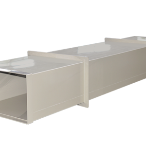
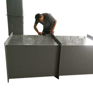
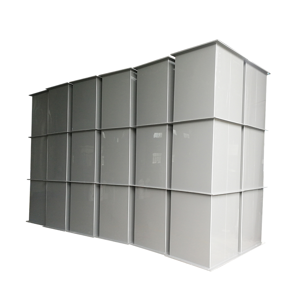
A standard rectangular duct section has flat walls that bow inward under negative pressure. Add flanges at the ends — and the flange does double duty: it provides the bolted connection surface AND it stiffens the duct end against collapse. Extend that logic: add intermediate flanges along the duct length, and they act as internal stiffening rings. A flange-reinforced square duct is a fundamentally different structural element than a plain rectangular duct — it handles deeper vacuum, spans further between supports, and provides serviceable joints without adding separate stiffening ribs.
For standard square duct specifications, see our PP Square Duct main product page.
Flange Types for Square Duct
| Flange Type | Construction | Best For |
|---|---|---|
| Integral welded flange | PP flat bar welded to duct end, face machined flat after welding. Bolt holes drilled on bolt circle pattern. | Permanent bolted connections at equipment interfaces, section joints requiring positive sealing, and anywhere the flange must resist bending. |
| Integral molded flange | Flange formed as part of the injection-molded duct section — no weld between flange and duct body. Available on standard profiles to DN1000. | Highest integrity: zero leak path between flange and duct. For critical exhaust carrying hazardous compounds. |
| Loose backing flange | Separate PP flange ring that slides over the duct end and bears against a stub-end or collar welded to the duct. Flange rotates freely for bolt hole alignment. | Field assembly where bolt hole alignment is difficult — the free-rotating flange simplifies installation. Also allows duct sections to be rotated relative to each other. |
| Intermediate stiffening flange | PP flat bar welded around the duct exterior at mid-span. Not a connection point — purely structural. Divides unsupported wall panel into smaller sections. | Increasing vacuum rating without adding separate rib stiffeners. Provides both structural function (stiffening) and service function (connection) at duct ends; structural-only at mid-span. |
Flange Design for Negative Pressure
A flange under negative pressure is loaded differently than a flange under positive pressure. Positive pressure tries to push the flanges apart — the bolts carry all the load in tension. Negative pressure tries to pull the flanges together — the gasket compression increases, which sounds good, but the real failure mode is the duct wall buckling just behind the flange where the stiffening effect of the flange ends:
- Flange thickness vs duct wall thickness. The flange must be stiff enough to distribute bolt clamping force uniformly around the gasket — typically 2-3× the duct wall thickness. A 5 mm wall duct uses a 10-15 mm flange. Undersized flanges create high and low spots in gasket compression — the low spots leak.
- Bolt spacing. Bolts spaced too far apart create unsupported spans between bolts where gasket compression drops below the sealing threshold. For PP flanges, bolt spacing should not exceed 4× bolt diameter for gasket pressures up to 1 MPa — roughly 40 mm for M10 bolts, 50 mm for M12. Wider spacing requires a thicker flange to distribute the load.
- Gasket compatibility. The gasket must be chemically compatible with the exhaust stream at operating temperature. EPDM for general service (-30 to 120degC), FKM/Viton for solvents and elevated temperature (to 60 °C), PTFE for aggressive mixed chemicals. A gasket that swells or degrades from chemical attack loses compression and leaks. For exhaust systems requiring EU Industrial Emissions Directive compliance, gasket material selection and flange face flatness are critical fugitive emission control points.
When Flange-Reinforced Duct Is the Right Specification
- Deep negative pressure systems (below -500 Pa). Standard rectangular duct walls begin deflecting at -200 to -400 Pa without reinforcement. Flange-reinforced duct with intermediate stiffening flanges at 500-800 mm spacing handles -800 to -1,500 Pa without additional ribs — the flanges themselves provide the stiffening.
- Long spans between supports. When support points are fixed by existing structure and cannot be added, flange-reinforced sections provide the necessary stiffness to span further without sag or vibration.
- Frequent disassembly required. Equipment that requires periodic removal for maintenance (fans, dampers, instruments) — flanged connections at both sides of the equipment allow removal without cutting duct. The flanges pay for themselves the first time you don’t have to cut and re-weld a section.
- Future expansion planned. Flanged blind connections at duct ends create tie-in points for future system expansion. Remove the blind flange, bolt on the extension, and the system grows without hot work.
For flange kits including gaskets and fasteners, see our Air Duct Connections & Flanges page.
Send your negative pressure specification and flange requirements to xicheng023@outlook.com. We’ll design the flange reinforcement and provide a complete quotation. WhatsApp: +86 18927456906.