
Incinerator exhaust is not boiler flue gas. The stream leaving a multiple-hearth, fluidized-bed, or rotary-kiln incinerator carries SO2, HCl, fine particulate, and trace metals at temperatures that require a quench stage before wet scrubbing equipment can operate. A so2 scrubber for incinerator exhaust is a wet absorption system that removes sulfur dioxide and hydrogen chloride together, cools the gas below the dew point of its acids, and holds up in an aggressive chloride environment — inputs that a boiler flue-gas desulfurization design does not capture. This guide covers how furnace type and feed set your SO2 and HCl load, which regulation fixes your design target, when a wet caustic route fits your conditions, and the design data a vendor needs. The result is a route decision plus a request-for-quote data sheet.
Key Takeaways
- A so2 scrubber for incinerator exhaust is a wet absorption system that removes SO2 while co-capturing HCl, quenching hot gas, and collecting a portion of the particulate in one train.
- Furnace type and feed determine load. Biosolids, municipal waste, and hazardous waste differ in sulfur and chlorine content, which sets your SO2 and HCl concentrations.
- Wet caustic (NaOH) scrubbing fits hot, chloride-laden incinerator exhaust when paired with a quench; dry and semi-dry routes have temperature and efficiency limits.
- The design target differs by regulation category. New SSI NSPS (40 CFR 60 Subpart LLLL) sets SO2 at 26 ppmvd, while existing units run under permits that can differ — a published example is 18 ppmv.
- pH, liquid flow, and pressure-drop monitoring are compliance evidence for SSI scrubbers, so they are design inputs, not optional instrumentation.
What an SO2 Scrubber for Incinerator Exhaust Is Designed to Do
The direct answer is that a so2 scrubber for incinerator exhaust is a wet absorption system that takes SO2 out of flue gas by contacting it with an alkaline liquid. On incinerator service it does four jobs at once, because the exhaust never arrives as clean SO2 alone:
| Function | What it does | Why it matters on incinerators |
|---|---|---|
| SO2 absorption | Alkaline liquor neutralizes sulfurous acid | The primary regulated pollutant and the reason the tower exists |
| HCl co-absorption | The same caustic circuit neutralizes HCl to sodium chloride | Chloride in the feed becomes HCl; two acid loads, one reagent loop |
| Gas quenching | Water spray cools hot exhaust to saturation before the absorber | Protects FRP/PP internals and condenses acid vapors into the liquor |
| Partial particulate collection | Spray and impingement capture a share of fine solids | Shares PM duty with downstream WESP or baghouse |
SO2 dissolves readily in water and forms a weak acid, which is why wet scrubbing works: the alkaline reagent neutralizes the acid and drives further absorption. The same liquid absorbs HCl, and because SO2 removal efficiency rises as the liquor pH increases, the pH setpoint is the primary control variable. This is the mechanism behind the wet route, and it is the same chemistry a vendor uses to size the tower.
Incinerator exhaust can leave the furnace well above 800°F (427°C). Wet scrubbers on this service include a quench section that cools the gas to saturation before the absorber, because FRP and polypropylene internals are rated below roughly 350°F. The spray and impingement action in the scrubber also removes a portion of the fine particulate and can co-capture condensed metals — a relevant effect on incinerators, where particulate and metals are regulated alongside SO2.
The wet route is not a default answer for every incinerator. It earns its place when the gas is hot, the acid load is mixed (SO2 plus HCl), and the facility already has or can add a scrubbing-liquor and blowdown management system. Those conditions are examined in the sections that follow.
Decision point: You can now state whether a wet scrubber addresses your exhaust — if SO2 and HCl are the target pollutants and the gas is hot, a wet train with a quench is the configuration to evaluate.
Incinerator Exhaust Is Not Boiler Flue Gas: What Determines Your SO2 and HCl Load
Incinerator exhaust differs from boiler flue gas in three ways that change the scrubber design: the pollutant load is set by the feed rather than by fuel chemistry, the gas arrives at higher temperature with more particulate and metals, and the acid mix is always SO2 plus HCl rather than SO2 alone. The load estimate starts with two inputs: furnace type and feed.
How the Furnace Type Changes the Load
Multiple-hearth (MH) and fluidized-bed (FB) furnaces are the two common sewage-sludge incinerator designs, and their emission profiles differ enough that EPA writes separate PM limits for them. New SSI NSPS sets the MH subcategory PM limit at 60 mg/dscm and the FB subcategory at 9.6 mg/dscm (40 CFR 60 Subpart LLLL, Table 1). The difference reflects more complete combustion and finer carryover in the FB bed.
The furnace also sets the gas conditions the scrubber sees. Multiple-hearth furnaces commonly burn in the 1,400–1,800°F range, fluidized beds typically run around 1,500–1,650°F, and rotary kilns frequently operate above 1,600°F. These are engineering expectations for screening, not guaranteed operating points — the exhaust analysis and stack data confirm the actual load.
Rotary kilns and liquid-injection incinerators handle waste streams with wider sulfur and chlorine swings. A kiln’s rotating bed and secondary combustion zone can stabilize burn, but the feed variability means the SO2 and HCl concentrations at the scrubber inlet swing with each batch. The practical consequence is the same for all furnace types: the scrubber must be sized on the highest expected acid load, not the average, because the regulation is a limit on the outlet concentration during operation.
Sulfur and Chlorine in the Feed
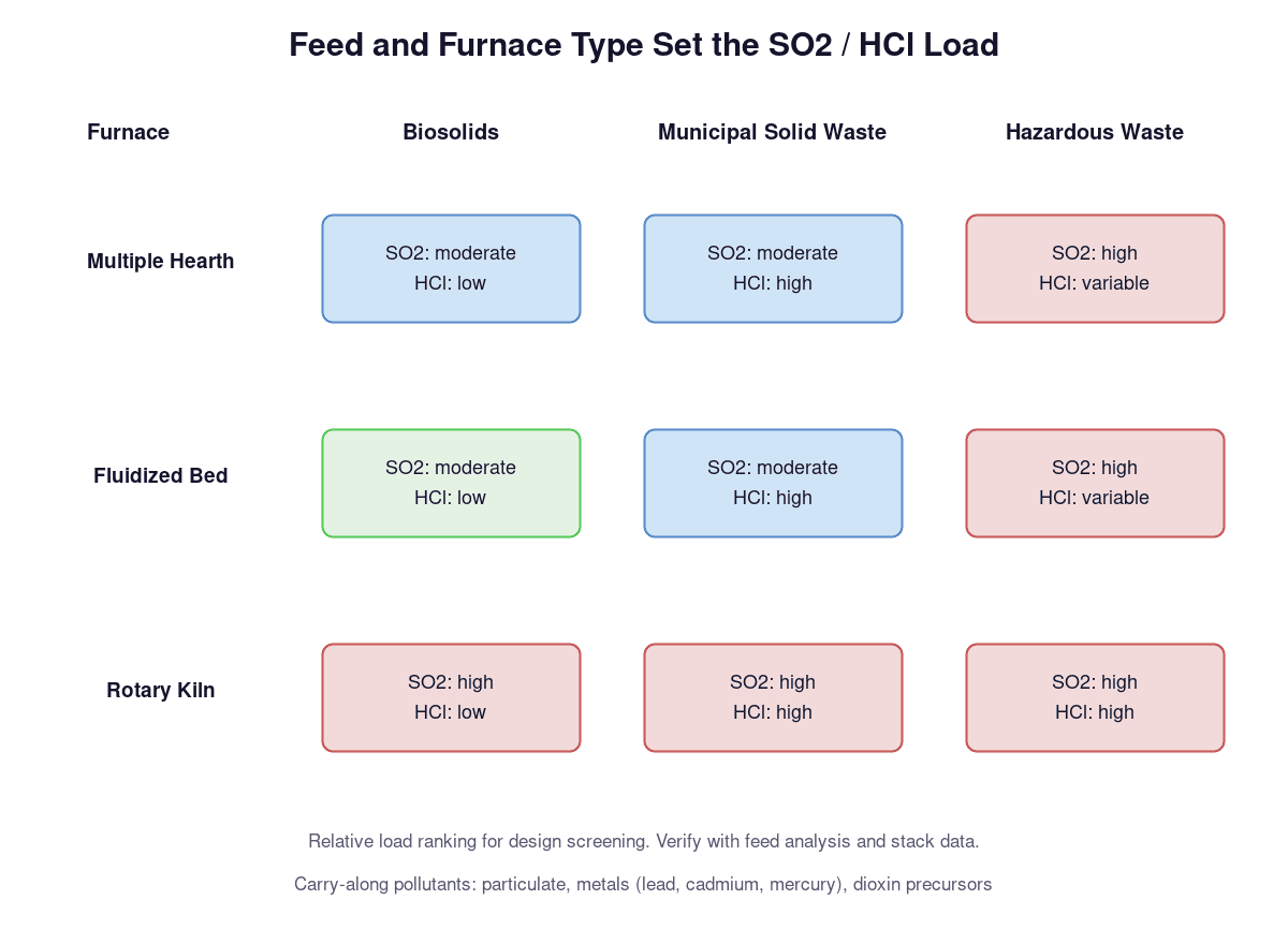
The feed, not the furnace, sets the acid load. Sewage sludge (biosolids) typically carries moderate sulfur and low chlorine; municipal solid waste (MSW) carries moderate sulfur with high chlorine; hazardous waste varies with the wastestream but can be high in both. These are engineering expectations for load ranking rather than fixed published values, and they explain why a scrubber specified for one feed cannot be copied to another without reviewing the analysis.
As a screening basis, dry-basis sulfur in dewatered biosolids commonly falls near 1–3% and chlorine near 0.3–1%; MSW runs lower in sulfur (roughly 0.1–0.4%) and higher in chlorine (0.5–1%); hazardous waste lots range wider in both. Treat these as relative ranges for load ranking, then confirm with the actual feed analysis. The same reasoning appears in the load map at the top of this section: biosolids across all three furnace types sit at moderate SO2 with low HCl, MSW at moderate SO2 with high HCl, and hazardous waste at high SO2 with variable HCl.
Chlorine in the feed becomes HCl in the exhaust, and HCl is the pollutant that drives material selection. The same caustic circuit that absorbs SO2 also absorbs HCl, so the two are treated together in the scrubber sizing. A facility burning biosolids in an MH furnace will typically see a different SO2:HCl ratio than a facility burning MSW, and the ratio determines how much of the reagent goes to SO2 absorption versus HCl neutralization.
Particulate, Metals, and Dioxin Precursors Riding Along
Incinerator exhaust carries a pollutant mix, not a single acid. Tri-Mer describes incinerator flue gas as including inorganic ash particulate, NOx/SOx, SO2, HCl, dioxins, and heavy metals (lead, cadmium, mercury) — a characterization consistent with EPA’s SSI rule, which regulates nine pollutants: PM, HCl, dioxins/furans, mercury, NOx, SO2, cadmium, lead, and CO (40 CFR 60 Subpart LLLL). A scrubber that only targets SO2 is incomplete for this service. Combustion SO2 and HCl are the acid-gas load here; hydrogen sulfide from upstream digester gas or tank vents is a separate stream with its own chemistry and scrubber design, covered in our H2S scrubber guide for wastewater and leachate tank vents.
The fine particulate and condensed metals matter to the wet scrubber in two ways. First, the spray and packed sections collect a portion of the particulate, so the scrubber shares the particulate removal duty with any downstream equipment such as a wet electrostatic precipitator (WESP). Second, the metal limits are tight — new SSI cadmium is 0.0011 mg/dscm and mercury 0.0010 mg/dscm — which means the facility decides where each pollutant is removed rather than assuming the SO2 scrubber handles everything. Equipment suppliers on SSI service also flag the fine mist and high dew point in this exhaust as the reason the gas must be conditioned before downstream treatment.
Decision point: From your furnace type and feed, you can now rank your expected SO2 and HCl load and list the co-pollutants your treatment train must carry (particulate, metals, dioxins) — the inputs needed for the regulation and route decisions next.
Which Incinerator SO2 Regulation Applies: NSPS Limits and Permit Limits
The regulation category, not the scrubber catalog, sets the outlet concentration your system must meet. Incinerators fall into EPA source categories with different rules for new units (NSPS) and existing units (emission guidelines and permits). Matching your unit to the right category comes first, because it fixes the design target and the monitoring obligations that the scrubber must support.
SSI: 40 CFR 60 Subpart LLLL and MMMM
Sewage sludge incinerators (SSI) are covered by 40 CFR 60 Subpart LLLL for new units and Subpart MMMM for existing units. New SSI SO2 is limited to 26 ppmvd, measured as a three-run average with Method 6 using at least 200 liters per run, or Method 6C with a one-hour minimum (40 CFR 60 Subpart LLLL, Table 1/2). The rule regulates nine pollutants: PM, HCl, dioxins/furans, mercury, NOx, SO2, cadmium, lead, and CO.
The SSI rule also assigns different PM limits to the two furnace subcategories: 60 mg/dscm for multiple-hearth and 9.6 mg/dscm for fluidized-bed units. This matters because the wet scrubber is often part of the PM control strategy, and the pressure-drop monitoring required for PM compliance is one of the operating parameters your scrubber design must support.
CISWI, HMIWI, and LMWC Categories
Commercial and industrial solid waste incineration (CISWI), hospital/medical/infectious waste incineration (HMIWI), and large municipal waste combustors (LMWC) are separate source categories under 40 CFR 60, each with its own subpart and limits. Manufacturers serving this market state scrubber compliance across CISWI, HMIWI, LMWC, and SSI categories, and the design logic carries over even though the numeric limits differ.
The practical point is that the category drives which subpart and which table applies to your unit. A scrubber specified from another category’s limits risks missing the applicable NSPS or permit value, so the first design input is the unit’s confirmed source category, not the pollutant list. Confirm the category with the responsible agency or permit before you lock the design target.
NSPS Limits vs Existing-Unit Permit Limits
New NSPS limits and existing-unit permit limits are two different legal lines and should not be mixed. The 26 ppmvd value above is the new SSI NSPS line. An existing incinerator may hold a permit limit that is tighter or looser depending on its operating permit and state requirements — a published biosolids incinerator project (Monroe Environmental packed-tower case study) was permitted at an SO2 limit of 18 ppmv, which shows that a permit value can be tighter than the NSPS default for a comparable unit.
For design, treat the applicable limit as the stricter of the two: the NSPS line if the unit is new, or the permit line if the unit is existing. The Monroe 18 ppmv example is a single project’s permit value, not a universal limit, so it serves as a design reference for “existing-unit permits can be tighter than the 26 ppmvd NSPS line,” not as a number to assume. Confirm the actual value with the permitting authority.
Decision point: You can now name your unit’s source category and state which limit line applies (new NSPS 26 ppmvd for SSI, or your existing-unit permit value) — the design target the scrubber must meet.
Wet Scrubbing vs Dry and Semi-Dry Routes for Incinerator Exhaust
The route decision is conditional: wet scrubbing is the strongest fit for some incinerator loads and the wrong fit for others. The three variables that separate the routes are gas temperature, whether HCl must be removed at the same time as SO2, and how much fine particulate and metal the facility must capture downstream. Wet, dry, and semi-dry approaches each have a window where they are defensible.
Where Wet Scrubbing Earns Its Place
Wet scrubbing earns its place when the exhaust is hot and the acid load is mixed. The same quench stage that cools 800°F+ gas to saturation also condenses acid vapors into the scrubber liquor, where SO2 and HCl are absorbed together by the caustic circuit. This makes the wet route the natural choice for incinerator exhaust, which arrives hot with SO2 plus HCl, rather than boiler flue gas where SO2 may be the only target.
Wet scrubbing also contributes to the metal and particulate picture. The spray and packed sections collect a portion of the fine particulate and condensed metals, and a downstream wet electrostatic precipitator can finish the job. Because new SSI metal limits are tight (cadmium 0.0011 mg/dscm, mercury 0.0010 mg/dscm), a facility planning to meet them typically needs a multi-stage arrangement, and the wet scrubber is a legitimate stage in that arrangement rather than a standalone answer.
Dry Sorbent Injection and Semi-Dry Limits
Dry sorbent injection (DSI) and semi-dry routes remove SO2 by injecting lime or sodium-based sorbents, then catching the solids in a baghouse or fabric filter. The semi-dry variant uses a spray dryer absorber that evaporates the slurry and leaves a dry product. These routes avoid the liquid handling and blowdown that a wet scrubber requires, which is their main attraction.
The limits are temperature and capture efficiency. DSI and semi-dry systems work best on gas that has already been cooled — duct injection typically runs at 300–400°F, and a spray dryer absorber discharges near 160–180°F depending on the slurry rate — and their SO2 removal efficiency is generally lower than a wet packed or venturi system when the acid load is high and variable. For incinerator exhaust carrying HCl and metals alongside SO2, the dry route must be paired with the same quench/conditioning logic, and the facility must still manage the collected sorbent and the metal-bearing residue. The practical comparison is wet versus dry-plus-baghouse, not wet versus nothing.
Multi-Stage Systems
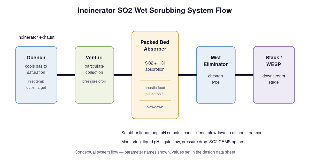
Incinerator emission control is routinely multi-stage. A common architecture is quench, then a venturi or packed absorber for SO2 and HCl, then a mist eliminator, with downstream equipment such as a wet electrostatic precipitator and carbon adsorption handling the metal and dioxin fractions that the scrubber does not fully capture (Tri-Mer describes this quench-to-carbon lineup on incinerator service). Each stage has a defined job, and the SO2 scrubber is one stage rather than the whole train.
The sequence follows the pollutant set: quench conditions the gas, the wet absorber takes SO2 and HCl, the WESP captures submicron particulate and condensed metals, and activated carbon adsorbs dioxins and mercury where required. Suppliers quote 99%+ SO2 removal on this type of multi-stage incinerator system, and manufacturers state compliance across CISWI, HMIWI, LMWC, and SSI categories. Design the stages for the pollutant list, not for SO2 alone.
Decision point: You can now state whether a wet route fits your conditions — hot gas with mixed SO2/HCl points to wet (with quench); dry routes fit when you accept lower capture and must still manage metal-bearing residue; multi-stage is the norm when metals and dioxins are regulated alongside SO2.
Reagent and Tower Configuration: Caustic, Lime, Packed Bed, and Quench
The reagent choice and the tower type are decided together, because the reagent sets the chemistry and the tower sets the contact. Incinerator exhaust is the case where caustic is the default reagent: it absorbs SO2 and HCl with the same circuit, and the pH can be controlled tightly enough to hold the outlet concentration at the design limit. Lime and limestone belong to larger, cooler gas streams where a gypsum byproduct is acceptable.
Caustic (NaOH) for Incinerator Loads
Caustic scrubbing runs the alkaline liquid through the tower, and the caustic consumes both SO2 and HCl in the same loop. The chemistry is straightforward: SO2 forms sulfurous acid in water, the caustic neutralizes it to sodium sulfite/sulfate, and HCl is neutralized to sodium chloride. This is why incinerator service defaults to caustic — the mixed acid load is absorbed without a second reagent system.
The pH setpoint is the control lever. SO2 absorption efficiency rises with liquor pH, so the system holds pH in a working band and feeds caustic to maintain it; the Monroe biosolids incinerator project ran 25% NaOH solution in a 316SS packed tower and met its permit. The byproduct is a liquid blowdown carrying sodium sulfite, sulfate, and chloride, which the facility treats or disposes rather than a dry solid.
Lime and Limestone: Where They Fit
Lime and limestone wet systems (FGD) are the large-flow route. They suit big gas volumes — utility and cement plant scale — where the reagent cost and the byproduct are the deciding factors. The limestone route produces gypsum, which can be dewatered to a residual moisture around 10% and sold or landfilled as a solid (GEA describes this gypsum handling on wet SOx scrubbers).
For incinerator exhaust, the fit is narrower. A sludge incinerator’s gas volume and acid load are usually small enough that caustic’s higher reagent unit cost is offset by the simpler single-loop design, and the HCl load is absorbed by the same caustic. Lime-based systems earn consideration when the facility already has a large FGD-type installation or when the byproduct must be a dewaterable solid, but they are not the default on this service.
Packed Bed vs Spray Tower vs Venturi
The three tower types differ in contact efficiency and particulate tolerance. A packed bed gives high gas-liquid contact over the full bed height and is the common choice for SO2/HCl absorption on incinerator service when the gas is already quenched and the particulate load is moderate — the Monroe project used a packed tower for exactly this reason. A spray tower uses nozzles rather than packing, tolerates more particulate, and is simpler, but transfer efficiency per stage is lower. A venturi achieves high-energy contact through gas velocity and is used when particulate collection matters; it is frequently a pre-stage ahead of the packed absorber in incinerator trains.
Selection follows the load: moderate particulate with SO2/HCl to absorb points to packed bed; heavy particulate or sticky carryover points to spray or venturi-first; high capture efficiency on both gas and particulate points to venturi plus packed. The mist eliminator above the packing catches entrained droplets before the gas leaves the tower.
Quench Tower Design Inputs
The quench stage protects everything downstream. Incinerator exhaust can enter well above the temperature rating of FRP and polypropylene internals (roughly 350°F), so the quench cools the gas to saturation before the absorber. The quench section is the hottest and most corrosive point, which is why suppliers specify high-alloy materials there — Hastelloy C276, 316L, or 304 — while FRP can serve below the temperature limit and PP/FRP in the cooler absorber section.
The quench also has a chemistry job: rapid cooling suppresses dioxin re-formation in the 400–700°F window where de novo synthesis can occur, and it condenses acid vapors into the scrubbing liquor rather than letting them reach downstream equipment. Design inputs for the quench are the inlet temperature, the saturation outlet target, the chloride concentration in the liquor, and the material of construction for that specific temperature range.
Decision point: You can now lock the reagent and tower configuration — caustic in a packed or venturi-plus-packed arrangement with a high-alloy quench is the working default for incinerator exhaust, adjusted up (venturi-first, more stages) as particulate and metals increase.
Design Inputs for an SO2 Scrubber for Incinerator Exhaust
The design inputs for an SO2 scrubber for incinerator exhaust are the numbers the vendor needs to size the tower, and the same numbers become the operating parameters the facility monitors for compliance. Liquid-to-gas ratio, pH setpoint, pressure drop, materials, and monitoring are not separate lists: they are one set that the design and the regulatory obligation share.
Liquid-to-Gas Ratio and pH Setpoint
Liquid-to-gas ratio (L/G) is the recirculation rate per unit of gas flow and sets the contact opportunity in the tower. Higher L/G increases absorption and reagent use but raises pump energy and tower size. The pH setpoint is the second lever: SO2 absorption rises as liquor pH rises, so the control system holds pH in a working band and feeds caustic to keep it there. The Monroe biosolids incinerator project demonstrates the practical range — a 316SS packed tower at 10,000 ACFM with 25% NaOH — and the same rule applies to sizing: verify L/G and pH against the inlet SO2 and HCl concentrations, not against a generic FGD table.
The reagent consumption follows from the inlet load. SO2 and HCl each consume caustic on a molar basis, so the design input is the expected maximum inlet concentration, not the average. Sizing on the maximum is what keeps the outlet below the limit line through feed swings.
Pressure Drop, Packing, and Mist Elimination
Pressure drop is both a design and a compliance number. The tower’s clean and loaded pressure drop determine fan sizing, and on SSI service the pressure drop across the wet scrubber is monitored for PM control compliance (minimum four-hour average, per 40 CFR 60 Subpart LLLL). A rising pressure drop signals packing fouling, which is the maintenance trigger on incinerator service where fine particulate loads the bed.
Packing selection balances contact area against fouling and pressure drop. Random packing in a countercurrent packed bed gives high SO2/HCl transfer and is the common choice for quenched incinerator gas; the mist eliminator above the bed catches entrained droplets before clean gas exits. The design input set is the clean-bed pressure drop, the expected loaded pressure drop at the design L/G, and the mist eliminator type (chevron is standard) sized for the carryover at full load.
Materials: Quench Section vs Scrubber Section
Material selection splits at the quench. The quench section sees the hottest, most corrosive gas and is specified in high alloys — Hastelloy C276, 316L, or 304 are the grades suppliers name on incinerator service (Tri-Mer) — because chloride attack at temperature defeats standard carbon steel. Below roughly 350°F, FRP becomes viable, and the cooler absorber section can use PP/FRP or a high alloy depending on the chloride concentration in the recirculating liquor.
The boundary is a chloride and temperature calculation, not a preference. Every point downstream of the quench operates saturated with acid-bearing moisture, so the design input is the chloride concentration in the scrubbing liquor at design pH and temperature. The material table follows from those two values, and the vendor confirms the grade against the specific liquor chemistry rather than copying the FGD specification.
Compliance Monitoring as a Design Input
The SSI rule turns operating parameters into compliance evidence. When a wet scrubber controls SO2 or HCl, the unit monitors scrubber liquid pH (minimum one-hour average) and liquid flow; when the same scrubber controls PM, cadmium, or lead, it monitors pressure drop (minimum four-hour average) and liquid flow (40 CFR 60 Subpart LLLL). These are not optional instruments — they are the record the facility keeps to demonstrate the scrubber ran within its design envelope.
The monitoring input also reaches the instrument choice. For SO2 CEMS, the rule sets a relative accuracy criterion when the inlet concentration is below 100 ppmvd: the mean of 20% or a 5 ppmvd absolute difference. That means the design must provide a representative measurement location and sample system, not just the control-loop instruments.
Decision point: You can now assemble the design input sheet for a vendor — L/G, pH setpoint, clean and loaded pressure drop, packing and mist eliminator, quench/absorber materials with the chloride basis, and the monitoring set (pH, liquid flow, pressure drop, SO2 CEMS option) your regulation requires.
Worked Example: SO2 Scrubber for a Sewage Sludge Incinerator
This example walks a full decision chain for a so2 scrubber for sewage sludge incinerator duty. It is an illustrative project — the numbers are a consistent design exercise for one set of conditions, not a XICHENG installation and not a guarantee of performance.
The Project Conditions
The facility is an existing sewage sludge incinerator in the United States. The unit is a multiple-hearth furnace burning dewatered biosolids, with an existing wet electrostatic precipitator (WESP) downstream for fine particulate and metal control. The gas flow at the quench outlet is 10,000 ACFM, saturated and cooled. Design assumptions for this exercise: inlet SO2 at 450 ppmvd, inlet HCl at 50 ppmvd, fine particulate moderate (the WESP carries the final metal duty). The unit is existing, so the design target is its permit line — set at 18 ppmv SO2 for this example, following the published biosolids incinerator project where a packed tower met an 18 ppmv limit.
The decision chain starts from these inputs and runs through the same modules as the earlier sections: load ranking, applicable limit, route, configuration, design inputs, monitoring.
Walking the Decision Chain
Load ranking: biosolids in an MH furnace, moderate sulfur and low chlorine, gives a mixed load of 450 ppmv SO2 and 50 ppmv HCl — the SO2 line dominates and HCl is present but modest. The nine-pollutant SSI picture applies, but the WESP downstream carries the metal and fine-particulate duty, so the scrubber’s job is acid gas.
Applicable limit: existing unit, permit line of 18 ppmv SO2. Required removal is (450 − 18) / 450 = 96.0% — a high-efficiency removal, which rules out a single-pass spray tower.
Route: hot gas with mixed SO2/HCl and a required 96% removal points to wet scrubbing with a quench. Route decision: wet.
Configuration: packed bed absorber with caustic, sized for the mixed acid load, with a high-alloy quench ahead of the tower. Liquid-to-gas ratio in the working range for packed-bed SO2 service (on the order of 8–12 gallons per 1,000 ACFM), pH held near the upper band of the working range to drive 96% removal. Materials: 316SS tower and 25% NaOH solution, matching the Monroe biosolids project configuration. Reagent estimate for this load: roughly 60 lb/h of 100% NaOH at the design inlet, before the HCl share is added — the vendor converts this to 25% solution consumption and tank sizing.
Monitoring: scrubber liquid pH and liquid flow recorded on the one-hour basis, pressure drop on the four-hour basis; the outlet verified by stack testing or CEMS per the permit. Result: a single wet caustic packed train meets the 18 ppmv permit line at the design load, with the existing WESP covering metals.
How the Result Changes If Conditions Change
If the inlet SO2 doubles to 900 ppmv at the same permit line, required removal rises to (900 − 18) / 900 = 98.0%. The packed tower can still reach that range with a higher L/G and tighter pH control, but the caustic demand roughly doubles and the packed bed sees more sodium sulfate loading — the design shifts toward a larger tower and more reagent storage.
If HCl rises to 200 ppmv (a waste stream change), caustic consumption climbs on the HCl side as well, and the chloride concentration in the liquor goes up, which pushes the material decision toward higher alloy grades in the tower. If fine particulate becomes a dominant load, a venturi stage ahead of the packed bed is added and the pressure-drop monitoring envelope widens, because the venturi is now part of the PM control train. Each change re-runs the same chain: load, limit, route, configuration, inputs.
Decision point: You can run this same chain on your own unit — list load, confirm the limit line, and derive route, configuration, and the design input sheet — to produce the single paragraph your vendor needs to start quoting.
Blowdown and By-Product Handling
A wet caustic scrubber produces a liquid blowdown, not a dry solid, and the byproduct form depends on the reagent and the oxidation state in the liquor. The blowdown route belongs in the design evaluation because it drives water treatment, reagent chemistry, and operating cost.
| Byproduct route | Reagent | Product form | Typical outlet | Handling |
|---|---|---|---|---|
| Caustic (NaOH) | Sodium hydroxide | Dissolved sodium sulfite/sulfate + chloride in liquid blowdown | Liquid, pH buffered near 6–9 | Wastewater treatment or deep-well disposal under permit |
| Lime/limestone | Calcium hydroxide/carbonate | Gypsum slurry, dewaterable | Solid at ~10% moisture | Landfill or sale as byproduct |
| Semi-dry sorbent | Lime or sodium sorbent | Dry mixed sorbent/salt/ash | Dry powder at ~140–180°F | Baghouse residue, landfill |
The table compresses the route decision into one screen: caustic keeps everything in the water phase, lime moves the sulfur to a solid, and semi-dry routes produce a dry mixed residue that still contains the absorbed sulfur and chlorine.
Gypsum vs Sulfite vs Sulfate Effluent
Caustic scrubbing produces sodium-based salts. The SO2 absorbed in the caustic circuit is neutralized to sodium sulfite, which can oxidize to sodium sulfate in the liquor; the HCl becomes sodium chloride. These stay dissolved in the blowdown, so the effluent carries the sulfur and chlorine load from the feed and must be treated or disposed of within the facility’s water permit.
Lime and limestone routes produce a different byproduct: gypsum (calcium sulfate), which can be dewatered to a residual moisture around 10% and handled as a solid (GEA describes this gypsum handling on wet SOx scrubbers). The solid route suits facilities that cannot take on a salty liquid blowdown. The choice between caustic (liquid effluent) and lime (gypsum solid) is therefore an effluent-management decision as much as a chemistry decision.
Downstream Treatment Interfaces
The blowdown does not disappear at the tower. It flows to the facility’s wastewater system, and its chloride and sodium loading must fit what that system can accept. On a sludge incinerator, the scrubber blowdown often coexists with other process streams — such as WESP purge water — and the combined flow is what the treatment plant sees, so the scrubber design should state the blowdown volume and composition at design load.
The design input is simple: blowdown flow rate, pH, dissolved solids, chloride, and the discharge destination. The vendor sizes the blowdown line and any dewatering step from these, and the facility confirms the stream fits its wastewater permit before the scrubber is ordered.
Decision point: You can now decide the byproduct route your facility can accept — caustic with liquid blowdown or lime with gypsum solid — and confirm the blowdown stream fits your wastewater system before you finalize the configuration.
Information Needed Before You Request a Quote
The request for quote fails when the data sheet is thin. The data to gather before you ask a vendor to quote is the same list the earlier modules produced: the load, the limit line, the route, and the design inputs, written as a data sheet rather than a description. This RFQ checklist is the deliverable that turns this guide into an action.
| Data item | What it sets |
|---|---|
| Furnace type and feed (MH/FB/rotary, biosolids/MSW/hazardous) | Load ranking, acid mix |
| Gas flow at the scrubber (ACFM) and inlet temperature | Tower and quench sizing |
| Inlet SO2 and HCl concentrations (ppmvd) | L/G, pH setpoint, reagent |
| Particulate and metals present; downstream equipment (WESP, baghouse) | Stage assignment, materials |
| Applicable regulation category and limit line (NSPS or permit) | Design target, monitoring set |
| Available reagents and byproduct route | Caustic vs lime, blowdown |
| Site constraints: space, utilities, wastewater discharge | Layout, blowdown interface |
| Material preference and chloride basis | Quench vs absorber grade |
Each row maps to a module in this guide, so a complete data sheet is the check that the decision chain was actually run. To see the sheet filled in, the worked example supplies the values: 10,000 ACFM at the quench outlet, 450 ppmvd SO2 and 50 ppmvd HCl at the inlet, an 18 ppmv permit line as the design target, and a 316SS packed tower with 25% NaOH as the configuration. A so2 scrubber for incinerator exhaust is specifiable in one pass when these inputs are confirmed; the vendor’s design then holds the tower to the limit line you named. When the route comes out wet, the SOx wet scrubber system covers the quench-and-absorber configuration this guide describes.
Decision point: You now have a complete request-for-quote data sheet for your incinerator SO2 scrubber — fill the eight rows, confirm the route and limit line, and the data you send is enough for a vendor to size the system.
Conclusion
Incinerator exhaust is a mixed acid, high-temperature stream, and the so2 scrubber for incinerator exhaust that fits it is a wet caustic train with a quench, a packed or venturi-plus-packed absorber, and a monitoring set that doubles as compliance evidence. The decision does not start with the scrubber catalog; it starts with the feed and furnace type, the applicable limit line, and the co-pollutants the facility must carry. Run the chain once, confirm the route, and the design input sheet is the document that makes the system specifiable.
The route and configuration stay conditional on conditions. Where the gas is hot and SO2 and HCl arrive together, the wet route earns its place; where the facility must meet tight metal and dioxin limits, the scrubber is one stage in a multi-stage train rather than the whole answer. Verify the applicable NSPS or permit limit with the responsible authority, confirm materials against your chloride and temperature basis, and treat the worked example as a method, not a spec. That method — load, limit, route, configuration, inputs — is what produces a data sheet a vendor can quote in one pass.


