
A wet scrubber project without a defined design basis fails in the same quiet way: bidders size to different duties, quotations cannot be compared, and acceptance tests have no fixed reference, so disputes follow. The common misconception is that the basis is a formality before the real engineering starts; in practice it is the real engineering, because every calculation and every guarantee reads from it. By the end of this guide you will be able to assemble your own wet scrubber design basis document, choose the operating cases — peak, continuous and turndown — that drive the design, and write acceptance values that can actually be verified under test.
Key Takeaways
- A wet scrubber design basis is the written duty-and-acceptance agreement a scrubber must be designed and verified against — and it comes before any calculation. Sizing outputs are only as trustworthy as the basis they start from.
- Seven elements make a usable basis: design cases, pollutant profile, operating envelope, reference conditions, limits, battery limits, and acceptance values.
- Acceptance values force testable language: a removal efficiency without a test method and boundary conditions cannot be proven at acceptance.
- Anchor the basis on the permit limit and the worst real process case; the other elements organize around those two anchors.
- Turndown and design margins are project-defined, not generic figures: set them from process load variability and agreement, never from invented standard ratios.
What a Wet Scrubber Design Basis Is — and Why It Drives the Calculation
A wet scrubber design basis is the written agreement on what a scrubber must handle and prove: the gas flow and pollutant load it must accept, the operating cases it must cover, and the acceptance values it will be tested against. A design basis is not a calculation. Sizing figures — diameter, packing height, liquid-to-gas ratio, pressure drop — come later, and they are only as good as the basis they start from, which is why defining the basis correctly is the first engineering decision, not an administrative formality. This module covers the elements of a design-basis document, the boundary between basis and calculation, and why the same document becomes the reference point for acceptance.
Design basis vs sizing calculation
The boundary is simple to state: the design basis fixes the duty and the acceptance rules, while the sizing calculation converts that duty into equipment dimensions — diameter, packed height, liquid-to-gas ratio, pressure drop, fan and pump duty. The conversion methods belong to a separate scrubber sizing calculation guide, which takes a fixed basis as its input. When the two roles are confused — a flow figure treated as a finished design statement when it still lacks a condition, or a vendor asked to invent the duty along with the geometry — the resulting quotations cannot be compared across bidders.
Responsibility follows the same split. The owner defines the duty, the operating cases and the acceptance terms, and confirms the vendor’s reading of the basis before fabrication; the vendor owns the calculation and its engineering assumptions. If a later dispute turns on which load the scrubber was really designed for, the basis document — not the calculation sheets — is the record that decides it.
What a design-basis document contains
A working design-basis document carries seven elements. First: design cases — peak and continuous gas flow, each with an expected duration and frequency. Second: the pollutant profile — composition, concentration, temperature, moisture, and how each changes with process time. Third: the operating envelope — the turndown requirement, expected load bands and upsets. Fourth: reference conditions — dry or wet basis, temperature, pressure and oxygen reference. Fifth: the limits the scrubber must meet — permit emission limits expressed as mass or concentration. Sixth: battery limits — what sits inside the scrubber package versus upstream and downstream scope. Seventh: acceptance values — guaranteed parameters, test methods, boundary conditions, and which party provides the operating state during the test.
Every element earns its place only if it can be verified. A flow without its temperature and moisture cannot be converted to a volume at design conditions; a removal efficiency without a test method and a boundary condition — inlet concentration range, load, temperature — cannot be proven at acceptance. A line that cannot be verified in a test or inspection is not a design input; it is a future commercial dispute. Acceptance values are listed last on purpose: recording what will be proved forces every earlier element to be stated in testable terms.
Where the basis starts: the permit and the process
A scrubber design basis starts from two anchors: the permit limit and the process that produces the gas. The permit sets the compliance target — a stack concentration or mass limit at defined reference conditions — and therefore decides which pollutants and which load the design must prove against. The process definition supplies the gas stream itself: how flow and load move through the operating day, which steps run together, and what happens during start-up, load swings and upset conditions.
A basis follows the target, not the reverse. An FCCU wet-scrubber project documented in a DigitalRefining case study revised its basis as New Source Performance Standards compliance was locked down — particulate below 1.0 lb per 1,000 lb of coke burn, sulfur dioxide removal above 90% — and the design was then proved across a range of operating cases rather than one snapshot point. Write the first version before the RFQ goes out, and expect it to change as permit conditions and process data firm up; the discipline is recording each change, not freezing the document.
Decision point: when you write your own basis, start with the permit limit and the process data that define the worst real case; the other six elements organize around those two anchors, and the acceptance-values element forces the testable wording — determine which of the seven your draft can verify before you finish it.
Choosing the Design Cases: Flow, Load and Pollutant Profile
The design cases you fix in the basis — peak, continuous, and the minimum operating point — decide the tower geometry, the liquid system, and finally what can be guaranteed. Choosing them is not a margin exercise done later by the vendor; it is a data-reading task you do first, from the process and the permit. This section shows how to convert flow and pollutant measurements into three defensible cases, and where turndown and margins come from.
Peak vs continuous load
Size the equipment volume to the peak, and size the operating basis to the continuous case. The sizing rule used in ventilation guidance for animal facilities is to handle the maximum exhaust airflow (LPELC wet scrubber guidance), which protects the tower against flooding and carryover at the worst moment of the day. The continuous load, in contrast, sets the steady operating point — the recirculation rate, reagent consumption and pressure drop the system lives at for most of its running hours.
A scrubber sized to the average and checked against the peak fails in a specific way: average sizing hides the peak, producing an oversized liquid system and an undersized tower. Record both cases with their durations — how many hours per day the scrubber runs near peak versus near continuous — because the duration split decides whether the vendor sizes for a short-duration surge or for a persistent high load, and those two designs are not interchangeable.
The pollutant profile: composition, temperature, humidity, variability
The pollutant profile is the composition table of the gas stream — which pollutants are present, in what phase, at what concentration, and at what temperature and moisture — plus how those values move over time. A packed-bed absorber designed for one compound at a steady concentration under-performs on a stream that changes shift to shift, because mass transfer and reagent demand follow the instantaneous load, not the average.
Temperature and moisture belong in the profile because they change the volume basis and the absorption chemistry: a hot, saturated stream condenses in an unheated duct and carries different contaminants downstream, and vapor pressure drives how much of a gaseous pollutant can be absorbed at the operating temperature. Capture the variability explicitly — minimum, maximum and typical, with timing — rather than a single average, so the design cases in the previous section have real data behind them.
Turndown: where it comes from
Turndown describes how far below the design point the scrubber must still run, normally and safely, and where that minimum sits. There is no generic turndown figure in the standards or the engineering literature, because the useful minimum is set by the process that generates the gas: a plant that runs one line at weekends has a different turndown need than one that runs full-out continuously. Define it from your own load history — the lowest sustained exhaust flow, its duration, and how often it occurs — not from a ratio another project used.
Once the minimum is defined, record what must remain true at that point: stable liquid distribution, no packing dry-out, no reagent starvation. Those are the constraints the vendor designs the internals and the control scheme against. If the process has no clear minimum because loads are continuous, say so in the basis; a declared operating floor beats an assumed one, and the owner supplies the load history, not the vendor.
Margins: what a margin covers and who sets it
A margin is a defined allowance for something specific — measurement uncertainty in the flow data, load growth, fouling over time — and it is only useful when the something is named. Naming it changes the design: an uncertainty margin lands on the instrumentation and control setpoints, while a growth margin lands on tower volume and pump capacity. An unnamed margin simply grows the equipment without a testable basis.
Two margins exist in every project and they must be written separately. The owner sets the basis margin, reflecting data uncertainty and future needs; the vendor applies its own internal design margin on top of the basis the owner confirmed. If both are folded into one unstated number, quotations become incomparable and the guarantee becomes ambiguous, so the basis should state who sets which margin and what each covers. Margins are therefore project-defined values, not standard figures, and any proposed number should come with its named cause and the party that owns it.
Decision point: fix the vessel size from the peak load and the operating and consumption figures from the continuous case; take turndown from your own load history, write every margin with its named cause and owner, and let these project-specific inputs decide the numbers — none of them transfer from another project.
Design Conditions and Reference Basis
Reference conditions are the fixed temperature, pressure, moisture and oxygen basis that every flow and concentration figure in the design basis is stated against — without them, a ppmv value and a mass limit cannot be compared, and a vendor and a regulator can read the same permit differently. For wet scrubber work the reference basis matters twice: once when you convert permit limits into design loads, and again when you check measured outlet values against those limits. This module covers how to write reference conditions, the mass-versus-concentration conversion trap, and where the scrubber package actually begins and ends.
Reference conditions: dry or wet basis, oxygen, temperature and pressure
Write every flow and concentration on a stated reference: dry or wet basis, temperature, pressure, and oxygen reference where a standard applies. A wet gas volume is smaller than the dry volume once moisture is removed, and a ppmv measured on a dry basis differs from the same gas measured wet; most combustion-standard limits, for example under 40 CFR Part 60, are expressed on a dry basis with a specified oxygen reference, while process-vent limits are often written wet.
State the actual conditions too: the design flow is the volume at scrubber inlet conditions — temperature, pressure and moisture as delivered — and every concentration conversion follows that same basis. The EPA packed-tower fact sheet (EPA-452/F-03-015) lists typical absorption-service inlet temperatures of 4–38 °C (40–100 °F) and notes that higher temperatures lower absorption rates and increase solvent or scrubbing-liquid evaporation; a hot stream therefore needs quenching or precooling before the packing, and that decision belongs in the basis, not in the vendor’s shop.
Concentration vs mass limits: why they are not interchangeable
A concentration limit and a mass limit are not directly comparable, and the conversion between them runs through the exhaust volume — not through the scrubber. A concentration in ppmv or mg/m³ says what is in each unit of gas; a mass limit in kg/h or lb/h says what leaves the stack per hour. The same mass emission at half the flow reads as twice the concentration, which is why a permit written in one form can be passed or failed depending on the flow the basis assumes.
Converted correctly, the arithmetic is straightforward: mass flow equals concentration times actual volumetric flow, corrected to the reference basis. The EPA fact sheet’s typical inlet range of 250–10,000 ppmv is a useful order-of-magnitude check for an absorption application — a value far outside that band is a sign the measurement basis or the application type is wrong, not a reason to reject the data. The trap is writing concentration and mass limits side by side without stating the flow and reference conditions each one implies, which turns the guarantee into two documents that contradict each other.
Battery limits and what belongs to the scrubber
Battery limits draw the line between what the scrubber package includes and what the rest of the plant provides, and they decide who owns each interface. In a typical package the line runs around the scrubber vessel and its immediate auxiliaries — recirculation pump, reagent dosing, controls, and often the fan and stack within the vendor’s scope — while upstream ducting, the process source, utilities and wastewater treatment stay with the owner or other packages.
The line matters commercially because every interface is a place where duties are assumed or missed: who condenses or pre-cools the gas before the flange, who supplies makeup water at the stated pressure, who neutralizes and disposes of the blowdown, and who bears the pressure drop of the connecting duct. State each interface in the basis with its condition and responsible party, consistent with the owner/vendor split established earlier: the owner defines the duty at the flange, the vendor confirms it inside the package.
Decision point: avoid the reference trap by stating one basis and converting everything to it, rather than writing a concentration and a mass limit side by side without the flow and reference conditions each implies; then let battery limits assign every interface, so you can determine who owns each condition and where the scrubber package ends.
From Basis to Guarantee: Parameters, Methods and Acceptance
A guarantee becomes an acceptance clause when three things are fixed together: the parameters being promised, the test method that proves them, and the boundary conditions under which the test counts. Most failed guarantees are not failed equipment — they are clauses missing one of those three, usually the boundary conditions. This module shows how to assemble all three from the monitoring indicators and test-method framework used for wet scrubbers, and where factory, site and performance testing fit.
Which parameters to guarantee
Use the same indicators that regulators use to monitor wet scrubber operation: pressure drop across the unit, liquid flow to the contactor, and outlet concentration, with gas flow, reagent addition and outlet temperature as secondary readings (EPA Monitoring Knowledge Base, wet scrubber for gaseous control). These three are not arbitrary: pressure drop and liquid flow are the operating conditions that make removal possible, and outlet concentration is the only one of the three that states the environmental result directly.
Removal efficiency belongs on the guarantee list, but only with the source conditions attached. Published EPA ranges put typical control-device estimates at 95–99% for inorganic gases, most absorbers above 90%, packed-tower absorbers above 99% for some pollutant–solvent systems, and particulate collection at 50–95% depending on application (EPA fact sheet EPA-452/F-03-015). None of these is a guaranteed number; the figure your supplier commits to for your stream, under the acceptance conditions, is proven by test, not assumed from a table.
Test methods to cite
Cite the test methods in the guarantee, not just the parameters, and cite them by their promulgated identity. For dry particulate, Method 5 of 40 CFR Part 60 defines the sampling train and gravimetric analysis (Method 5: Particulate Matter); for volatile organic compounds, Method 18 specifies gas-chromatographic measurement of the collected sample (Method 18: Volatile Organic Compounds); and Methods 1–4 set the velocity, sampling-point, gas-composition and moisture determinations every concentration result depends on (EMC promulgated test methods; 40 CFR Appendix A-1).
Naming the methods removes the biggest loophole in an acceptance clause — a removal efficiency promised without a definition of how it will be measured, by whom, and on what basis. Once the methods are fixed, the guarantee statement becomes testable: inlet and outlet sampling points, the reference conditions from the previous module, and the averaging time for the concentration result are all part of the same citation. Copy the method number and the version into the clause rather than paraphrasing it.
Boundary conditions of a guarantee
Every guaranteed value needs its boundary conditions: the load range, inlet concentration range and temperature range inside which the guarantee holds, plus the operating state the test runs at. A removal efficiency guaranteed at the design point is meaningless if the acceptance test is allowed to run at half load on a low-concentration day; the clause must state the envelope and the test conditions together.
Responsibility follows the split used throughout this document: the owner provides the operating state — representative feed stock, the stated load and concentration band — and the vendor executes the test and stands behind the measured result within that state. Write into the clause who supplies the test stream, who pays for the third-party stack-test contractor where one is required, and what happens to the guarantee if the owner cannot supply the stated conditions. An assignment for each of those items is what makes the clause enforceable rather than descriptive.
FAT vs SAT vs performance test
Factory acceptance testing (FAT), site acceptance testing (SAT) and the performance test verify different things, and only the performance test proves a guarantee. FAT is the vendor’s shop test of the assembled unit against hydraulic and mechanical requirements; SAT confirms installation, safe operation and interface conformity after site assembly; the performance test — typically a stack test against the reference methods — verifies the promised outlet concentration and removal efficiency on the real stream. This three-way split is procurement convention, not a regulatory requirement, and the contract defines the scope of each stage.
Plan the three stages in the basis so each result feeds the next decision: FAT gives the vendor the green light to ship, SAT gives the owner a unit ready for loaded operation, and the performance test closes the loop on the guarantee values written earlier. A guarantee survives only if the acceptance test inherits the same parameters, methods and boundary conditions the clause names — which is why the acceptance clause is the direct translation of the design basis into contract language.
Decision point: check your own guarantee clause against three questions — parameters from the monitoring indicators (pressure drop, liquid flow, outlet concentration) plus a committed removal figure, methods cited by number, and boundary conditions with the party supplying the test state named; the element usually missing is the last one, so decide which of the three your draft lacks before you send it out.
Verification and Handover: Acceptance Testing into Operation
Acceptance testing does not end with a signed report; it fixes the baseline that in-service monitoring compares against for the life of the unit. What the acceptance test could not prove — or was not allowed to run — becomes the first item the operating team must watch. This module covers what the acceptance result sets up, the handover to in-service monitoring, and what happens when a guarantee cannot be verified at all.
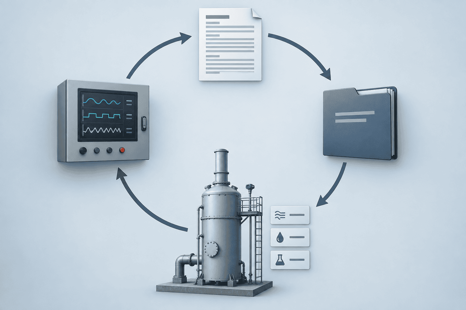
Closed loop from process data to design basis to acceptance verification to in-service monitoring. Conceptual illustration, not measured project data.
What acceptance testing sets up
The measured result from the performance test becomes the reference point for the operating data that follow: a clean, verified state — design pressure drop, design liquid flow, a known outlet concentration at a known load — against which later readings are judged. Without it, every future drift is an argument about what the unit was ever capable of; with it, a drift is a measurable deviation from a documented value.
That reference value belongs in the handover package together with the operating limits it implies: the load band and reagent setpoints that produce the tested result, and the warning boundaries near the tested envelope. What the acceptance test did not cover — a pollutant absent during the test, a season not sampled — is listed explicitly as an unverified area, so the operating team does not assume the guarantee extends where it was never proven.
Handover to in-service monitoring
After acceptance, responsibility for keeping the unit at the proven state moves to the operating team, and the questions change from contract language to daily readings: is pressure drop drifting, is liquid flow holding, is outlet concentration staying where the test left it? In-service performance diagnosis and recovery — baselines, monitoring pillars and threshold evaluation — are covered separately in our scrubber performance testing guide, which takes over where this page stops: this page covers purchase and delivery acceptance; that guide covers operating-period diagnosis and recovery.
The split is deliberate and matches the two documents’ boundaries: a guarantee dispute belongs to the acceptance record, while a slow efficiency loss two years into service belongs to the diagnostic procedure. Keep the acceptance report with the unit’s commissioning file, and hand the same baseline values to the monitoring program so both documents read from one set of numbers; whichever party owns the operating data, the reference point does not change.
When a guarantee cannot be verified
A guarantee that cannot be verified is not automatically void — it is a clause that never came into effect, and the disposition depends on why verification failed. If the owner never supplied the stated operating state, or the method could not be executed at the installed configuration, or the data have too many gaps for a defensible result, the outcome is a project-specific question, not a standard answer: the contract terms set the remedy, and no generic clause can be quoted here without inventing one.
Write the contingency into the original clause so it does not have to be negotiated after the fact: what counts as the owner’s failure to provide conditions, what retest window exists, and whether the guarantee converts to a reduced-scope commitment or a joint diagnostic program under the in-service guide. The honest position is that unverifiable guarantees are resolved by agreement, and the best time to agree is before the test, not after it.
Decision point: only a tested guarantee leaves you a reference value to monitor against — and when the question turns from the acceptance record to operating drift, your next step is the performance-testing guide.
Worked Example: Building a Wet Scrubber Design Basis and an Acceptance Clause
This worked example walks a wet scrubber design basis end to end, from load data to a draft acceptance clause, using the sequence of the previous modules. Everything here is worked-example assumptions: the project data are invented, every number carries a unit and a stated condition, and no value is a quotation or a promise. Replace the inputs with your own measured data and the same steps produce your own design-basis document and a clause structure ready for quotation.
Example project data (worked-example assumptions)
An acid pickling line vents to a packed-bed wet scrubber. Measured flow is 10,000 CFM at 30 °C, near-saturated, at the scrubber inlet flange; the permit limit is an outlet concentration of 5 ppmv HCl (wet basis, 25 °C, 101.3 kPa reference). Inlet HCl runs 50–150 ppmv: the 150 ppmv peak lasts about 40 minutes per 8-hour shift, typical load is 60 ppmv for most running hours, and the lowest sustained flow is 5,000 CFM when one line stands idle at weekends. These are the inputs the basis must organize.
Peak sets vessel sizing, continuous sets operating and consumption figures, and 5,000 CFM sets the turndown floor. Margins are written separately by agreement: a ±10% flow-measurement allowance for instrument uncertainty and a +20% future-line growth allowance on vessel volume, both owner-declared in the basis, with any vendor internal margin stated on top. All of these figures are worked-example assumptions for this page only.
Step 1–4: from load to basis
Step 1 fixes the design cases: 10,000 CFM with the 150 ppmv peak as the sizing case, 60 ppmv continuous as the operating case, and 5,000 CFM as the turndown minimum, each with its duration. Step 2 writes the seven-element document from the first module — design cases, pollutant profile, operating envelope, reference conditions, limits, battery limits and acceptance values — so every later figure reads from one table rather than from memory.
Step 3 converts the limit onto one reference basis: 5 ppmv HCl at reference conditions becomes a mass hourly figure through the design exhaust volume, which is the concentration-versus-mass conversion applied correctly rather than side by side. Step 4 selects the guarantee parameters from the monitoring indicators — pressure drop, liquid flow, outlet concentration — and drafts the acceptance clause below, with the removal figure left as a placeholder for the committed value.
Example acceptance clause (structure; values to be filled per project)
The clause below shows the structure a guarantee needs — parameters, methods, boundary conditions and responsibility — with every numerical value left as a placeholder. It is a worked-example template, not a commitment: no vendor has quoted these figures, and copying the clause into a contract without filling the placeholders from a project quotation would be an error.
- Parameters: outlet HCl concentration ≤ [x] ppmv; committed removal efficiency [x]% at design conditions; pressure drop ≤ [x] Pa at design flow; recirculation liquid flow ≥ [x] L/min. (Placeholders — not quoted values.)
- Test method: stack test per the promulgated method applicable to the pollutant and installation under 40 CFR Part 60; sampling points, reference basis and averaging time per the design-basis document.
- Boundary conditions: inlet HCl 50–150 ppmv; gas flow 5,000–10,000 CFM; inlet temperature 25–35 °C, near-saturated; the guarantee holds only inside this envelope.
- Responsibility: the owner supplies the stated operating state and representative feed stock; the vendor executes the test and stands behind the measured result within the envelope; third-party stack testing and its cost per contract.
With the placeholders filled, the clause inherits everything the earlier modules built: the reference conditions keep the concentration result comparable, the boundary envelope comes from the turndown and margin decisions made in the example, and the named method makes the removal figure testable during the performance test. The same document then hands the verified baseline to in-service monitoring under the performance-testing guide.
Decision point: re-run this sequence with your own stream data — flow, concentration band, durations and permit limit — to assemble your own seven-element wet scrubber design basis and a placeholder acceptance clause; once the acceptance test verifies the filled figures, you can now hand that baseline to the in-service monitoring guide for the operating phase.
FAQ
What is a wet scrubber design basis?
A wet scrubber design basis is the written set of inputs, operating cases and acceptance rules a scrubber must be designed and verified against. It is the document described in the first section of this guide: seven elements from design cases and pollutant profile through reference conditions, limits and acceptance values. Everything downstream — sizing, quotation and guarantee — reads from it.
How is peak scrubber load calculated?
This guide does not calculate peak load; it defines the basis the calculation needs. Decide the peak from process data — the highest sustained exhaust flow with its duration — and hand that case to the engineer who performs the sizing, because the conversion belongs to the scrubber sizing calculation guide. The turndown and margin decisions from the design-cases section apply here, not a generic formula.
What does a scrubber performance guarantee cover?
A performance guarantee covers three linked elements: the parameters promised (pressure drop, liquid flow, outlet concentration, and a committed removal figure), the test method that proves them, and the boundary conditions — load, concentration and temperature range plus the operating state — inside which the guarantee holds. Responsibility for supplying conditions and executing the test is part of the same clause.
Who runs the acceptance test: vendor or owner?
The owner supplies the operating state — the stated load, concentration band and feed stock — and the vendor executes the test and stands behind the measured result within that state. A third-party stack-test contractor may run the measurements where the contract requires independence, and who pays for it is part of the acceptance clause. FAT and SAT follow the same division.
Can a design basis be changed after ordering?
Yes, but only as a recorded change, because a design basis is an evolving document while targets firm up. Write each change with its date, reason and affected values, then re-run the affected acceptance parameters, since the guarantee clause inherits the latest basis and an unrecorded change silently invalidates the acceptance reference. This change discipline is project practice, not a regulatory rule.
Conclusion
Your wet scrubber design basis is the first engineering decision, not an administrative step. Write it before the calculation begins, and size the cases from your own process and permit data rather than from vendor defaults — that ordering, basis first and calculation second, is what makes quotations comparable and guarantees testable. Let the acceptance clause inherit everything the basis fixed: the monitoring parameters, the promulgated test methods and the boundary conditions all read from the same document, so a guarantee verifies the original commitment instead of starting a new negotiation.
After acceptance, hand the verified baseline to the performance-testing guide, which owns operating-period diagnosis and recovery; this page stops at that handover boundary. And treat the worked example for what it is — an illustration built on assumed inputs — re-running it with your measured stream data before any figure enters a contract. Check each of the seven elements against a record you can actually produce, and you have closed the loop from load data to a verifiable acceptance value; your team, your vendor and your acceptance test then all read from one document.


