
Choosing the right polypropylene grade and the right packing media is what decides whether a wet scrubber still performs in year five, and it is the part of the specification that a standard model table cannot carry. PP is chemically inert to HCl, HF, H₂SO₄ and mixed acid fumes, but its temperature and oxidizer limits — and the grade and wall thickness actually supplied — decide service life and structural margin.
This guide covers material and model selection: which PP grade suits which duty, how packing media change pressure drop and fouling at the same gas and liquid loading, and how the standard 3,000–45,000 m³/h model range maps to airflow and tower diameter. The general sizing calculation — inputs, diameter, L/G, packing height, pressure drop, fan and pump power — is covered on the scrubber sizing calculation guide linked further down this page.
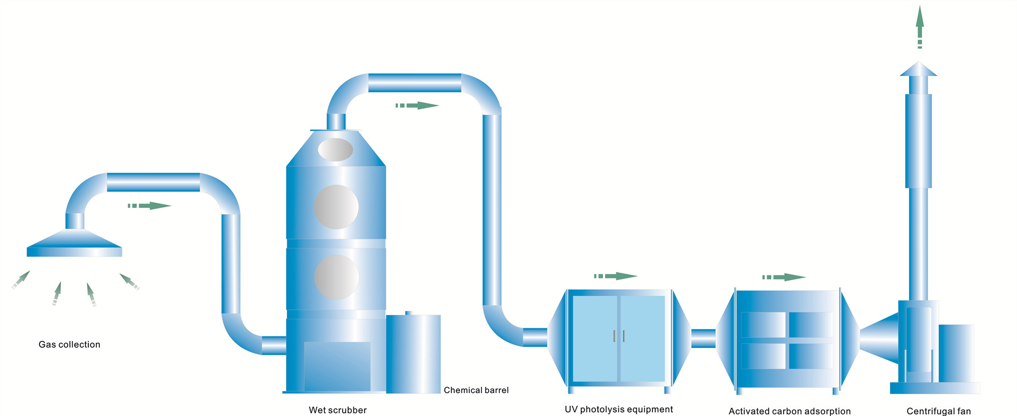
Table of Contents
For specifications and pricing, browse our wet scrubber product catalog.
Key Takeaways
- PP grade selection is a duty decision, not a preference. Concentration, temperature under load, oxidizer content and fabrication method decide which grade is defensible, and the choice has to be documented against supplier data rather than assumed from the fact that PP is chemically inert.
- Packing media decide pressure drop and fouling at the same gas and liquid loading. Compare random and structured packing on those two terms plus mass-transfer data, not on price or on a claimed universal cost multiplier.
- Specific surface area must come from the selected supplier’s geometry. A figure quoted from a catalogue page for a nominal size is not a performance guarantee, because the same nominal size differs between suppliers.
- The model table screens models; it does not select them. Airflow band and tower diameter narrow the choice, and the hydraulic, chemistry, structural and compliance checks confirm it.
- Nothing here replaces the sizing calculation. Velocity, L/G and packing height follow from the flooding fraction and from the packing supplier’s data, which the general sizing workflow on this site sets out.
Worked Example: PP Scrubber Selection for HCl Fume Extraction
Step 1: Define the Exhaust Parameters
An electroplating facility needs to size a PP wet scrubber for HCl fume extraction. The measured exhaust airflow is 8,000 m³/h. The inlet HCl concentration is 150 mg/m³. For this example, assume the applicable authority sets a 10 mg/Nm³ outlet limit and that inlet and outlet concentrations use the same reference basis. The gas temperature is 35°C (ambient). The duct run from the pickling line to the scrubber is 25 meters.
Step 2: Calculate Design Airflow
Using an illustrative 15% project margin: Q_design = 8,000 x 1.15 = 9,200 m³/h. Check duct leakage separately from the leakage specification; length alone is insufficient. From the model selection chart, select XC-PP-10000 (8,000-12,000 m³/h range), preliminary tower diameter 1,400mm, subject to a hydraulic check.
Step 3: Calculate Required Removal Efficiency
eta_required = [(150 – 10) / 150] x 100% = 93.3% The inlet and outlet values give 93.3% required removal. This worked example uses a 97% design target; set the final margin from project risk and compliance requirements.
Step 4: Set L/G Ratio and Packing Height
HCl is highly water-soluble, but L/G and depth depend on chemistry, temperature, packing, wetting, and hydraulics. This example assumes L/G = 2.0 L/m³ and 3.5 m packing height in two stages (2.0 m + 1.5 m); validate both values with project data.
Step 5: Verify Compliance
At L/G = 2.0 and packing height 3.5m with standard PP Pall ring packing: Outlet HCl = 150 x (1 – 0.97) = 4.5 mg/Nm³ This is below the example 10 mg/Nm³ limit but not below 3 mg/Nm³. The applicable EU BAT-AEL depends on sector and reference conditions. The calculation supports only the example limit. For detailed cost comparison
of this scrubber configuration, see our acid scrubber cost guide.
How Packing Media Selection Affects Scrubber Sizing
The packing media inside the scrubber determines how much contact area is available for gas-liquid mass transfer. Choosing the wrong packing can force you to oversize the tower or accept lower removal efficiency.
Random Packing: Raschig Rings, Pall Rings, Saddles
Random packing is dumped into the tower and settles naturally. Pall rings are a common random-packing option, but specific surface area must be reported in m²/m³ and taken from the selected supplier’s geometry. Pressure drop, efficiency, fouling behavior, and price must be compared at the same gas and liquid loading. For HCl, HF, and SO₂ applications, packing size must be verified against hydraulic, wetting, solids, and mass-transfer requirements.
Structured Packing for High-Efficiency Applications
Structured packing uses ordered corrugated channels and may provide different surface area and pressure-drop characteristics from random packing. Its suitability for a limited tower height or a less-soluble gas must be checked with supplier hydraulic and mass-transfer data. It does not have a universal cost multiplier or guaranteed tower-diameter reduction. For a complete comparison
of packing types, see our packing media selection guide. Browse our PP packing media products for specifications and pricing.
Standard PP Wet Scrubber Model Selection Chart (3000-45000m³/h)
Full Range Standard Model Specification & Core Parameter Matching Table
The table below presents preliminary PP wet scrubber matching for the illustrative 3,000–45,000 m³/h range. Use it for preliminary model screening, then complete the hydraulic, chemistry, structural, and compliance checks.
| Standard Model | Design Airflow Range (m³/h) | Tower Diameter (mm) | Optimal Empty Tower Velocity (m/s) | Recommended Packing Height (m) |
|---|---|---|---|---|
| XC-PP-3000 | 2500-3500 | 800 | 1.2-1.8 | 2.0-3.0 |
| XC-PP-10000 | 8000-12000 | 1400 | 1.3-1.9 | 3.0-4.0 |
| XC-PP-20000 | 18000-22000 | 2000 | 1.4-2.0 | 4.0-5.0 |
| XC-PP-30000 | 28000-32000 | 2400 | 1.4-1.9 | 5.0-6.0 |
| XC-PP-45000 | 40000-45000 | 3000 | 1.3-1.8 | 6.0-8.0 |
Adjustment Rules for High Concentration, High Temperature & Special Working Conditions
Special working conditions require targeted adjustments when you size a PP wet scrubber, to maintain efficiency and PP material reliability. For inlet pollutant concentration over 2000mg/m³: Increase tower diameter by 10%, add a second packing stage, and increase L/G ratio by 40% to ensure full pollutant absorption. For inlet gas temperature
above the selected PP grade’s allowable temperature under load: evaluate pre-cooling and verify supplier data. Set the airflow allowance from measured variability and design uncertainty. For explosive or dust-laden
exhaust: characterize the hazard and complete the applicable explosion assessment. Filtration, velocity, classification, isolation, venting, or suppression must follow that assessment.
2026 Global Industrial Emission Standard Compliance Validation for Each Model
Compliance validation is the final critical step when you size a PP wet scrubber. A model in the selection chart does not automatically meet the EU Industrial Emissions Directive, a US EPA NESHAP rule, or China’s GB 37822-2019 requirements. Applicability, pollutant limits, averaging periods, reference conditions, and test methods must be checked for the specific facility and process. For each model
, validate that the calculated removal efficiency meets the local emission limit, with documented test reports for inlet and outlet pollutant concentrations required for regulatory inspections. Additional compliance requirements apply for pharmaceutical, electronics, and chemical manufacturing industries, with stricter emission limits for hazardous air pollutants (HAPs) in 2026.
Where the Sizing Formulas Live
This page covers material and model selection: which PP grade survives the chemistry, temperature and oxidizer load, which packing media to specify, and which standard model fits the airflow band. The general sizing calculation itself — the five inputs, column diameter, L/G, packing height, pressure drop, and fan and pump power — is worked through on the scrubber sizing calculation guide.
Material and Model Selection Mistakes to Avoid
The sizing and compliance pitfalls that used to be listed here are covered on the scrubber sizing calculation guide linked above. What stays specific to this page is the material side: choosing a PP grade without checking the real concentration, temperature and oxidizer load; comparing packing media on price instead of on pressure drop and fouling at the same gas and liquid loading; and picking a model from its airflow band alone, without the hydraulic and chemistry checks that a model table cannot carry.
Commissioning: Verifying the Installation
After installation, validate that the scrubber performs as designed. These 5 checks confirm your sizing calculations were accurate:
- Measure actual airflow at the scrubber inlet with an anemometer. Compare to design airflow. Acceptable range: plus or minus 10%.
- Test inlet and outlet concentrations using portable gas analyzers or laboratory sampling. Verify removal efficiency meets the design target.
- Check pressure drop across the packing bed. Compare with the clean, wetted baseline and supplier curve at the same flows. A higher reading can indicate fouling, blockage, loading, flooding, or a flow/instrument change; channeling is one possible cause.
- Verify liquid distribution by inspecting the packing surface through the sight glass. Dry spots indicate maldistribution that reduces efficiency.
- Confirm sump pH control operates correctly. The dosing pump should follow the project setpoint and control logic for the pollutant, reagent, probe location, and process lag.
Document all commissioning data for regulatory inspections. Facilities regulated under OSHA PEL limits and US EPA NESHAP standards must maintain stack test records demonstrating continuous compliance. See our scrubber performance testing guide for detailed diagnostic procedures.
Frequently Asked Questions
How do I calculate the right scrubber size for my facility?
Start with your exhaust airflow rate (m³/h) and pollutant concentration (mg/m³). Determine the liquid-to-gas (L/G) ratio from chemistry, minimum wetting, packing hydraulics, and validated mass-transfer data, then use the 3,000–45,000 m³/h model chart only for preliminary screening. For mixed-contaminant streams, check each credible operating case and derive any project margin from measured variability and design uncertainty.
What happens if I undersize a wet scrubber?
Undersizing causes three cascading problems: pollutant removal efficiency drops below compliance limits, packing media fouls faster due to inadequate liquid distribution, and reagent consumption spikes as the system tries to compensate. Retrofitting can add demolition, duct modification, installation, commissioning, and downtime costs; quantify those items for the facility rather than applying a universal multiplier.
Can I use the same sizing method for HCl, HF, and odor scrubbers?
The core sizing principles are the same, but the design parameters differ significantly. HCl scrubbers need higher L/G ratios and deeper packing beds than odor scrubbers. HF scrubbers require additional considerations for fluoride removal efficiency and special packing materials. Each pollutant type has its own minimum contact time and bed depth requirements.
What is the standard model range for PP wet scrubbers?
Our standard PP wet scrubber range covers 3,000 to 45,000 m³/h in airflow capacity. Models are available in both vertical and horizontal configurations. The model selection chart in this guide provides preliminary matches for airflow, diameter, packing volume, and pump capacity that still require hydraulic, chemistry, structural, and material verification.
Do I need to oversize my scrubber for future capacity increases?
If capacity will increase, include the future flow in hydraulic, fan, pump, and turndown checks. Later packing or stage additions require prior allowance in the vessel, supports, distribution, utilities, and access.
What compliance pitfalls should I watch for when sizing?
The three most common pitfalls are: designing for average emissions instead of peak loads, ignoring temperature effects on gas density and volume flow, and failing to account for altitude corrections. Each of these can reduce your actual removal efficiency by 5–15% compared to the design specification.
How does packing media type affect my scrubber size?
Packing media with higher surface area allows a smaller tower diameter or shorter packing bed to achieve the same removal efficiency. For example
, switching packing geometry changes surface area, wetting, capacity, fouling, and pressure drop. Recalculate height from supplier mass-transfer and hydraulic data; surface area alone is insufficient. The optimal choice balances capital cost, operating cost, and required removal efficiency.
How do I know if my sizing was correct after installation?
Run the commissioning performance test at the time required by the permit, startup plan, and approved test method. Measure inlet and outlet pollutant concentrations, airflow rate, and pressure drop. If outlet concentration
is below the emission limit with at least 20% margin, and pressure drop is within the design range, your sizing is correct. If efficiency is below target, check liquid distribution, packing condition, and L/G ratio before assuming the tower is undersized.


